Get the Red Out
Using simulation to predict high-conductivity insert performance.
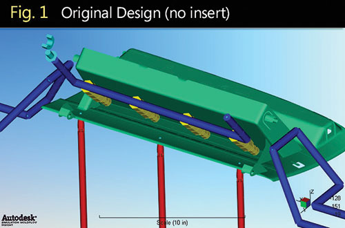
Fig. 1 Original design; no insert.

Fig. 2 Revised design with BeCu insert added.

Fig. 3 Comparison of surface temperature at same cooling time.
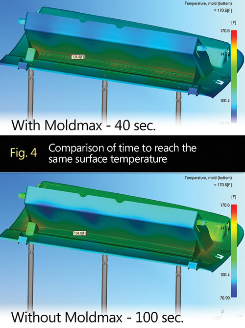
Fig. 4 Comparison of time to reach the same surface temperature.
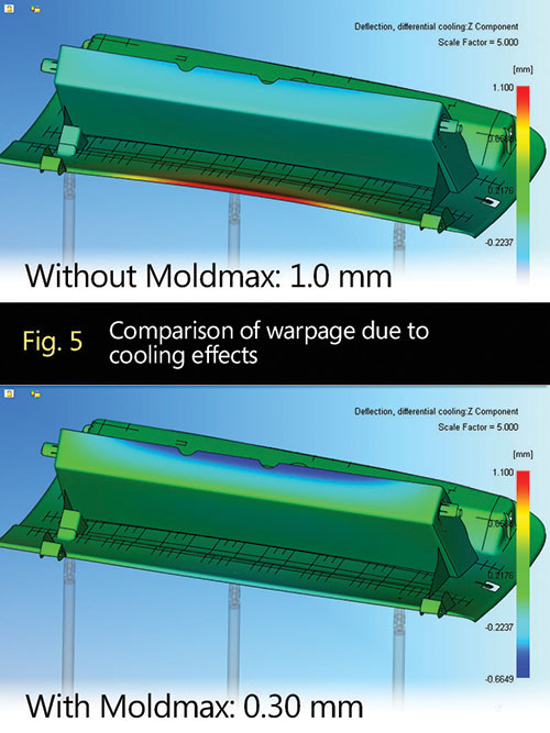
Fig. 5 Comparison of warpage due to cooling effects.


Do you remember the old Visine commercials from the ‘70s, ‘80s and ‘90s that showed us how easily you could “get the red out” of your tired, weary eyes with just a drop or two of the product? I don’t know why, but I was wowed by the prospect of being able to make such a dramatic change in someone’s eyes with just a couple of drops.
Recently, I was working on a cooling analysis project that reminded me of those commercials. I started thinking, “If only someone could invent something like that for cooling injection molds!” Just put a couple drops of solution on your hot spots, and, bingo–instant cooling relief for thousands of cycles. A boy can dream, can’t he? Until this dream because a reality however, we’ll have to stick with what we know, and we’ll use simulation to get there.
What we know is this: molten plastic that is injected into a mold has to be cooled. It must be done uniformly and in a timely fashion. Otherwise, you are left with not only low-quality parts, but expensive ones due to longer cycle times. It can’t get much simpler than that, can it?
Unfortunately, for complex shapes, getting that heat out of the mold is the hard part—especially considering all of the things that get in the way and make it difficult for a moldmaker to use straight-drilled water lines to reach some areas of a part. These include mold action, ejection, inserts, hot runners, gating, etc.
Indeed, one of the more-challenging aspects for the moldmaker to handle is tight geometry—areas where there is a deep pocket between two or more adjacent walls of a part that are very close to one another. Oftentimes, you either can’t get a straight drill into those areas because of thin steel conditions, or you don’t want to because the drill size would be so small that the coolant flow would be too restrictive. It’s easy enough for the moldmaker to just let it be, as he doesn’t have to live with the problem day after day like the molder does; however, any conscientious moldmaker will take the next step and try to improve the cooling of that area. One way to do that is with higher-conductivity inserts.
Making Your Move
You can look at this from two angles: cycle time and part quality. Let’s focus on the cycle time aspect first. What would it mean to your company if you could consistently make molds that outperform your competitors’ molds in terms of cycle time?
That’s a hard one to gauge because you cannot directly compare molds built by two moldmakers. But believe me, molders will notice. They know what they quoted for cycle time on every mold, and if your molds can consistently come in under that number, then you have a leg up on your competition when you are bidding on future work.
On the part-quality side, the same principle applies: if you can consistently design and manufacture molds that deliver better part quality, your customers will take notice, and you will develop a reputation that also puts you ahead of your competition.
Both of these ideas are obvious, but what is not so obvious is figuring out when you should make the move to include those higher-conductivity inserts. This is where cooling simulation comes in. Using a cooling analysis tool to predict the differences between a standard cooling design and one using high-conductivity inserts helps a mold designer make the decision about whether or not they should be used.
However, as I’ve stated in previous articles, the best simulation results come from experienced users who do this kind of analysis work day in and day out. Experienced analysts will know how to create an appropriate simulation model with the proper insert properties, so that the results can be trusted.
Accepting all the defaults in the analysis program isn’t always the best choice. For example, experienced users will know when it is appropriate to use an aggregated mesh solver and when it is not. They will also know how to interpret the various cooling analysis results, including when to use part surface temperatures versus part average temperatures. In a previous article (MMT, April 2013), we talked about circuiting cooling lines appropriately. The experienced analyst will know how to do that to get the most out of the water lines.
When performing a cooling analysis, one should go through the following steps:
1. Determine ballpark cycle time by getting most of the part to an acceptable temperature for ejection.
2. Evaluate surface temperature uniformity across and between core and cavity surfaces.
3. Improve hot spots by using direct cooling wherever possible.
4. Introduce beryllium copper (BeCu) inserts in areas where direct cooling is not possible.
5. Circuit cooling lines for optimal temperature rise and coolant flow.
Every material has a different temperature at which it is rigid enough to withstand ejection forces, therefore, the target temperature for ejection is different for every material. Let’s say we’re using a polypropylene (PP). We might target an average wall temperature of around 140°F. For a PC/ABS, we might target 185°F. Once most of the part is within +/- 5°F of that target, we should feel comfortable with where we’ve set the cooling time.
Dealing with Hot Spots
From there it is an exercise in trying to deal with hot spots in the easiest way possible, such as moving cooling lines around until it the temperature is acceptable, or determining whether more drastic means are necessary, such as BeCu inserts.
The areas with tight geometry mentioned earlier are usually the ones that demand attention. It is in these areas that we can start playing “what if” with BeCu inserts. In the beginning stages of our analysis (see Figure 1), we assume that the whole mold is made from one material (for example, P20). We assign thermal properties to it, and no additional geometry modeling is necessary. However, when we add BeCu inserts, it is necessary to model those inserts explicitly (see Figure 2).
Initially, we’ll put in a generic insert with some rough dimensions just to see what types of improvements we might get. Along with modeling the BeCu insert, it is critical that direct cooling be placed inside it. It doesn’t need to be close to the part surface, but it does need to be inside the insert so that we don’t end up with a block of metal that gets overheated faster. A BeCu insert that has no direct cooling is thermally isolated from the rest of the mold, whereas one with direct cooling provides a path for the heat to get out.
At this point, we run a simulation using the same cooling time as in the first analysis, and we usually find a significant drop in temperature (see Figure 3). Oftentimes, this temperature is well below that of the rest of the part. If that is the case, we can now start reducing the cooling time until the temperatures in that area start to match the rest of the part. The result is often a significant improvement in cooling time. In our example, it took 60 fewer seconds to reduce the temperatures in the problem area to those of the rest of the part (see Figure 4).
Our example is one of not only reduced cycle, but improved part quality as well. In this case, the original cooling design was responsible for 1.0 mm of the total warpage. By improving the cooling, the temperature differential between the two sides of the part was reduced, thereby reducing the contribution by the cooling design to the warpage to 0.30 mm in the opposite direction (see Figure 5).
The example we’ve shown is a fairly dramatic one for which the benefits are very clear. When the gains aren’t nearly as dramatic, it may boil down to an economic decision. In those cases, the ROI must be evaluated, looking at the total cost of manufacturing the BeCu inserts versus the cycle time gains. These costs include the additional material, along with additional EDM time and special considerations for handling BeCu.
Summary
So the next time you’re looking for a way to improve your molds with BeCu inserts but are not sure if it’s worth it, consider using cooling simulation to help make the decision. Experienced analysts will be able to tell you not only what kind of cycle time gains you might expect, but also whether or not you will see an improvement in the warpage of the part, and that will assist you and your customers in “getting the red out.”


Related Content

What You Need to Know About Hot Runner Systems and How to Optimize Their Performance
How to make the most out of the hot runner design, function and performance.
Read More
5 Hot Runner Tips for Moldmakers and Molders
Best practices for initial hot runner tryouts and effective preventive maintenance.
Read More
Breaking Down Hot Runner Maintenance
Improving a manifold’s maintenance plan requires specific skills and knowledge of its functioning areas.
Read More
Hot Runner Truths, Myths and Overlooked Areas
Addressing hot runner benefits, improvements and everyday issues from the perspective of decades of experience with probably every brand on the market.
Read MoreRead Next

Are You a Control Freak?
Using simulation to determine the right valve gate sequence.
Read More
Are You a Moldmaker Considering 3D Printing? Consider the 3D Printing Workshop at NPE2024
Presentations will cover 3D printing for mold tooling, material innovation, product development, bridge production and full-scale, high-volume additive manufacturing.
Read More
How to Use Strategic Planning Tools, Data to Manage the Human Side of Business
Q&A with Marion Wells, MMT EAB member and founder of Human Asset Management.
Read More