
Get More Coolant Flow Through Smaller Bubblers
This method for calculating the size of nonround water passages is designed to increase coolant flow, and reduce pressure loss and cycle time.
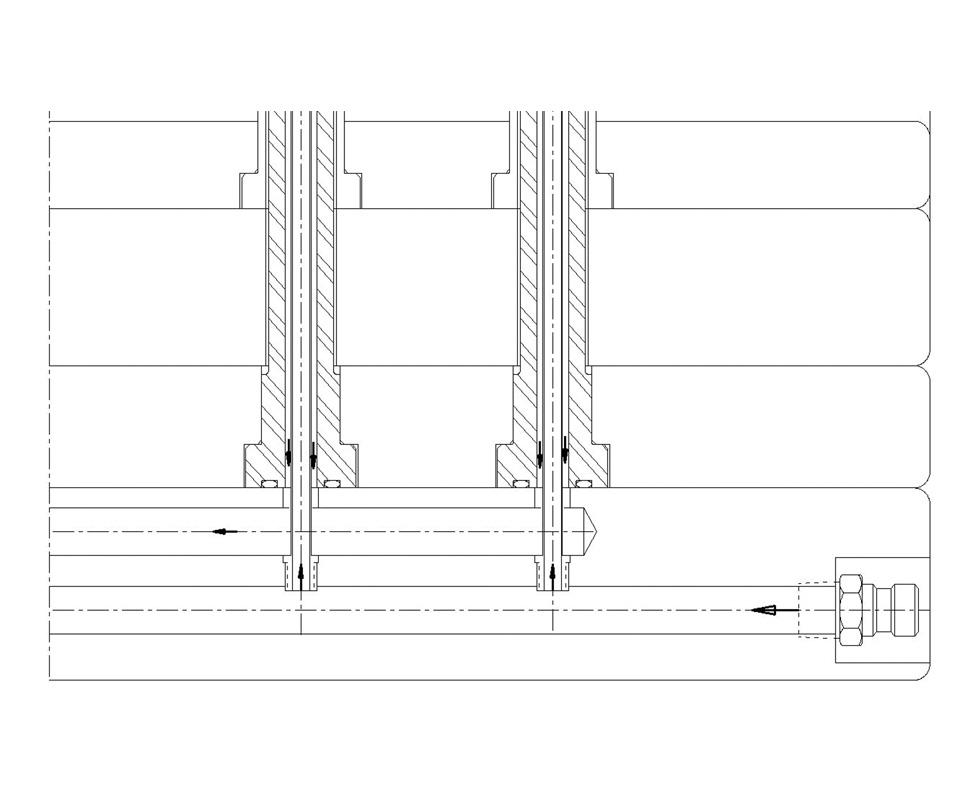
Figure 1 - Most mold designers are familiar with a parallel arrangement of water lines to feed bubblers. Figures courtesy of DZynSource LLC.
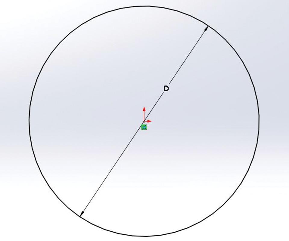
Figure 2 - The hydraulic diameter of a round passage is equal to the hole’s diameter.
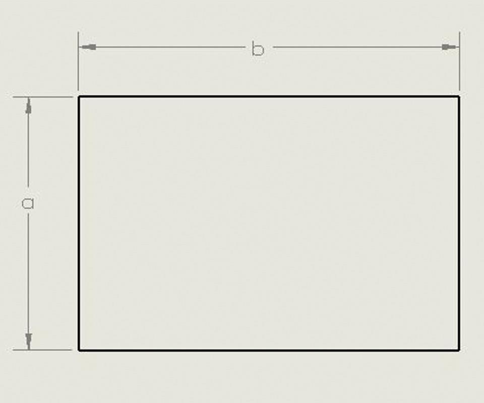
Figure 3 - The hydraulic diameter of a rectangular passage equals four times the area of the rectangle divided by the perimeter.
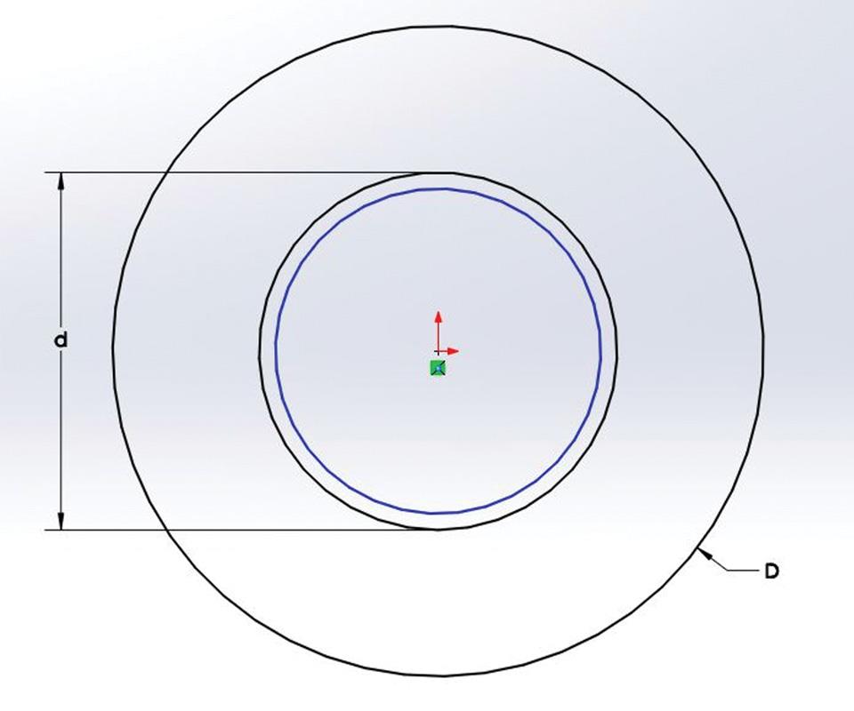
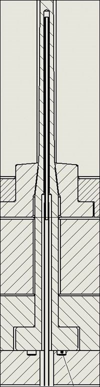
Figure 4 - The annular channel is the area between the hole diameter “D” and the outside of the bubbler “d.” The formula for hydraulic diameter is dh = (D - d).


Most mold designers are familiar with designing a parallel arrangement of water lines, whether when designing water manifolds or circuits to feed bubblers, such as in Figure 1. It’s a pretty straightforward process: The area of the drilled sublines is calculated, and then a feeding line size is chosen that has at least as much area as the total area of the lines being fed.
However, what if the channels to be fed are not round? Some examples would be a cooling channel around a round cavity or a bubbler residing in a drilled hole. Most moldmakers and mold designers have been taught that the cooling channel area should be equal to or smaller than the area of the hole that feeds it, regardless of the shape. This works for round channels, but problems arise when trying to design non-round passages, including annular ones.


Here, I will present an alternative method for calculating proper non-round channel sizes to optimize coolant flow with minimal pressure losses.
Hydraulic Diameter
While reading fluid mechanics books for writing software, I stumbled upon the equivalent hydraulic diameter method for determining water channel sizes. Those in the heating, ventilation and air conditioning trades have been using this calculation for years to size ventilation channels and duct work, but I have never seen it used in plastics or tooling. This method is only used on nonround shapes to calculate the size that an equivalent round passage would be, based on a ratio of the area of a nonround passage’s cross section to that passage’s perimeter.
When designing nonround passages, the hydraulic diameter is also substituted for diameter “d” in equations used to determine laminar or turbulent flow and pressure losses, and to define friction factor and relative roughness. Fortunately, the area and perimeter of the shapes in question usually no longer need to be calculated manually, as that information can usually be extracted from today’s CAD software.
More elaborate methods for fluids calculations exist, but the hydraulic diameter equation can provide reasonable results accurately and quickly. The exact equation is:
dh = 4 A / p
(in which “dh” is the hydraulic diameter, “A” is the area section of the passage, and “p” is the perimeter of the passage).
The application is always the same, regardless of whether the shape is round, square or irregular:
Round. If we test this equation on a round passage (see Figure 2) in which “π” represents the ratio of a circle’s circumference to its diameter and “D” is its actual diameter, we get:
dh = 4 A / p
A = π D2 / 4
p = π D
so
dh = ((4 (π D2 / 4)) / π D).
Because the 4s and πs in this last equation cancel out, we are left with:
dh = D2 / D
dh = D.
The results are as expected. In a round passage, the hydraulic diameter is the same as the actual diameter.
Rectangle. If we then test the hydraulic diameter of a rectangular duct or pipe (see Figure 3) in which “a” represents the width/height of the passage and “b” is the height/width of the passage, we get:
dh = 4 A / p
A = ab
p = 2a + 2b = 2 (a + b)
so
dh = (4 (ab)) / (2 (a + b))
dh = 2 ab / (a + b).
Notice the difference between calculating a feeder line for the rectangular passage using the equivalent area calculation and using the hydraulic diameter equation. Assume the rectangle is 0.200 by 0.300 inch with an area of 0.060 square inch. The area calculation method would imply a diameter of 0.2764 inch, but the hydraulic diameter calculation indicates that the effective passage is smaller at 0.240 inch. The reason for this is that the circle has the most efficient perimeter-to-area ratio of all of the planar geometric shapes. The sphere is the most efficient volume.
The fluid has a stationary boundary layer at the walls of the fluid passage, and the fluid shears as it reaches maximum velocity at the passage’s center. This is similar to polymer flow, except the velocity profile is much less parabolic due to water’s lower viscosity. This means that the fluid velocity goes from zero at the boundary to maximum velocity at a level not too far from the boundary in less-viscous materials. Viscous materials, like plastic, reach their maximum velocity at the center of the flow passage.
As the shape of passages deviate from round, the perimeter increases relative to the area of the opening. As the length of the perimeter increases, the pressure to force fluids through the passage increases, due to the increased shear forces.
Annular. Using the industry standard method of equivalent area to calculate the size of bubbler tubes, and the holes that they reside in, results in undersized drilled holes or oversized bubblers with truly excessive pressure losses, clogged lines (especially with the smaller tubes) and longer-than-necessary cycle times. So, if we apply the hydraulic diameter to an annular channel (see Figure 4, page 24):
dh = 4 A / p
A = π / 4 (D2 - d2)
p = (πD - πd)
so
dh = (4 (π / 4 (D2 - d2))) / (πD + πd).
Because the 4s and πs cancel out, we are left with:
dh = (D2 - d2) / (D + d).
You may recognize (D2 - d2) from high school algebra and the FOIL (first, outer, inner, last) method of multiplication: (D + d)(D - d) = (D2 - d2). If we use this substitution in the numerator, we arrive at:
dh = (D + d)(D - d) / (D + d)
(dividing numerator and denominator by (D + d)). Then we end up with a very simple calculation of:
dh = (D - d).
Flow Outside of a Bubbler Tube
The hydraulic diameter of the area between the outside of a bubbler and the inside of a drilled hole is simply the drilled-hole diameter minus the bubbler outside diameter. Consequently, the drilled-hole diameter that provides an equivalent hydraulic diameter outside the bubbler can be calculated by adding the bubbler’s inside and outside diameters.
In one example, a supplier-published chart shows a bubbler with an outside diameter of 0.437 inch, an inside diameter of 0.307 inch and a recommended channel size of 0.531 inch. These sizes are based on what we have all been taught about “the areas being equal inside and outside the bubbler.” In order to have the annular channel’s hydraulic diameter be equivalent to the inside diameter of the bubbler, the hole would have to be 0.737 inch in diameter (0.531 + 0.307). This is especially important with smaller bubblers that are prone to clogging.
The concept of hydraulic diameter may seem counter-intuitive, as you can get more fluid flow and less pressure drop with a smaller bubbler when the hole size is kept constant (if it was calculated by the equivalent area method). This is because the excessive pressure loss is caused by the restriction of flow outside the bubbler when using the equivalent area method to size the holes. I have actually increased water flow and reduced cycle time in existing molds by moving to a smaller bubbler when the hole size must be kept constant.
Simple Solutions
Some suppliers offer high-flow tubes for water bubblers. These are thin-wall tubes with an integral thread available in two different sizes for each tube diameter. There are high-flow tubes with a larger tube for each thread and ones with a smaller tube for the same thread. If you check your bubbler and hole sizes, and discover that your mold was designed with these parts sized using the equivalent area method and that your mold has the high flow tube with the larger tube for the given thread size, simply make a new bubbler with the smaller tube version. This will immediately increase flow rate, decrease pressure drop and potentially reduce cycle time. (Keep in mind that this may not always work, however, as there are many others parameters that could be controlling cycle time.)
The bottom line is that any non-round water channel has a higher-pressure-loss and Reynolds number than its area would indicate. A solution is to use the hydraulic diameter equation to design larger non-round channels.
Here is an example of the application of the equivalent hydraulic diameter method in mold design: A customer’s mold had a parallel water design feeding eight cores/bubblers in a row. The water entered at a lower level, flowed up inside the bubbler tube and down the outside, returning to the upper-level water line and out of the mold. The mold was originally built with a standard-sized, equal-area-based drilled hole and bubbler.
The hole in each core was 0.093 inch (3/32), and the high flow tube had a 0.072-inch outside diameter with a 0.060-inch inside diameter. During the mold’s first run, only 0.5 gallons per minute flowed through the row of eight cores. The pressure on the feed side was 85 psi, and the pressure on the outlet side was 5 psi. This water circuit was experiencing a 75-psi pressure loss to get a half-gallon per minute of water flow through the circuit.
The core’s drilled hole could not be enlargered any further, so the bubbler tubes were redesigned by cutting the existing 0.072-inch-diameter bubbler until it was in the larger relief diameter behind the 0.094-inch drilled hole. Next, a bubbler with an 0.059-inch outer diameter was welded inside of the 0.072-inch bubbler, which resulted in a smaller bubbler inside the 0.094-inch drilled hole. When reconnected to the water source, the new flow rate increased to 6 gallons per minute with only a 20-psi pressure loss. Using a smaller bubbler yielded more flow with less pressure loss.


Related Content

MoldMaking Technology's Most-Viewed Content 2022: Products
MMT shares the five top-viewed technologies, equipment and services of 2022 in each Engineer, Build, Maintain and Manage tenet based on Google Analytics.
Read More
Mold Innovations Power Unique Auto Lighting Elements on Hummer EVs
Diamond machining, electroforming of micro-optical inserts and modified latch-lock system help injection molds produce unique forward lighting elements.
Read More
Fundamentals of Designing the Optimal Cooling System
The right mold components can help improve mold cooling and thereby produce higher-quality parts.
Read More
Advancing the Mold With New Technologies
This roundup is full of products and services that help answer concerns and meet needs for the industry. Featured in this roundup are hot runners, mold components, mold materials and more.
Read MoreRead Next

Are You a Moldmaker Considering 3D Printing? Consider the 3D Printing Workshop at NPE2024
Presentations will cover 3D printing for mold tooling, material innovation, product development, bridge production and full-scale, high-volume additive manufacturing.
Read More
How to Use Continuing Education to Remain Competitive in Moldmaking
Continued training helps moldmakers make tooling decisions and properly use the latest cutting tool to efficiently machine high-quality molds.
Read More
Reasons to Use Fiber Lasers for Mold Cleaning
Fiber lasers offer a simplicity, speed, control and portability, minimizing mold cleaning risks.
Read More