
Gaining Control of Five-Axis Mold Machining
The CNC motion system is key to tackling the tight tolerances and superior finishes of modern mold manufacturing.
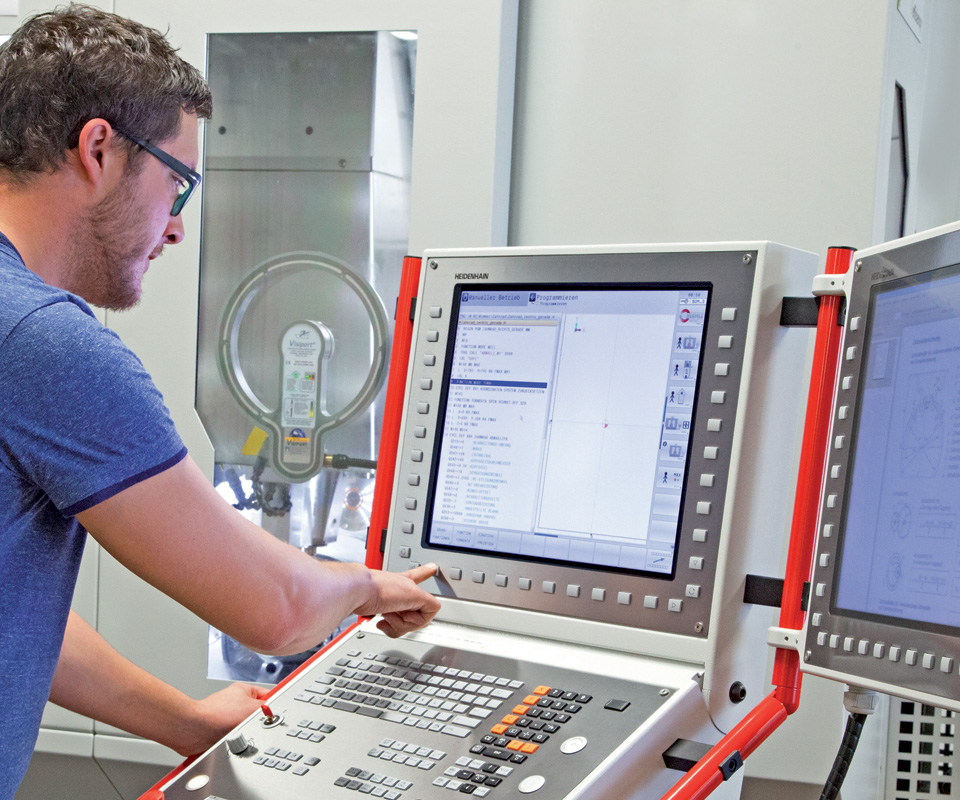
Precise control of acceleration and deceleration along a programmed contour while also considering machining time, surface quality and geometric accuracy can be achieved with a CNC control that uses an approach optimized for the milling machine and the manufacturing process. The CNC control pictured here has a secondary monitor option to access CAM system data.
Tool center point management provides effective control of contour tolerance. This is an important function for 3D surface machining, as it ensures consistent chip load, which improves tool life, part accuracy and surface finish. (Image courtesy of Heidenhain Corp.)
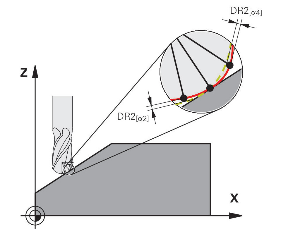
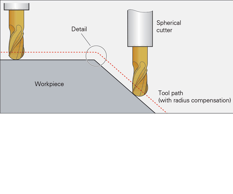
Three-dimensional tool radius compensation is used to define angle-dependent delta values that describe the tool deviation from the ideal circular form. This is important for form accuracy when using cutting tools with nose/side radii.
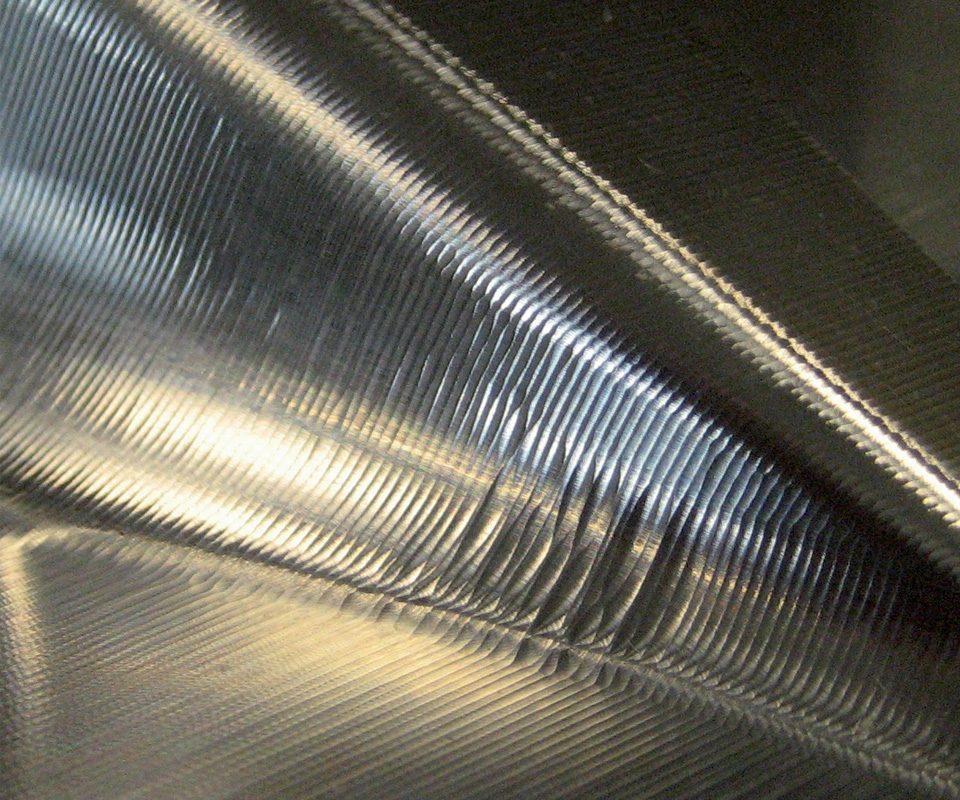
The surface quality of this workpiece is unacceptable.
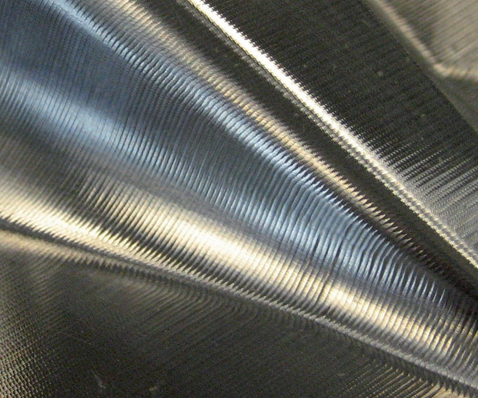
The milling machining result created using the proper CNC motion system, shows the high reproducibility of adjacent paths.
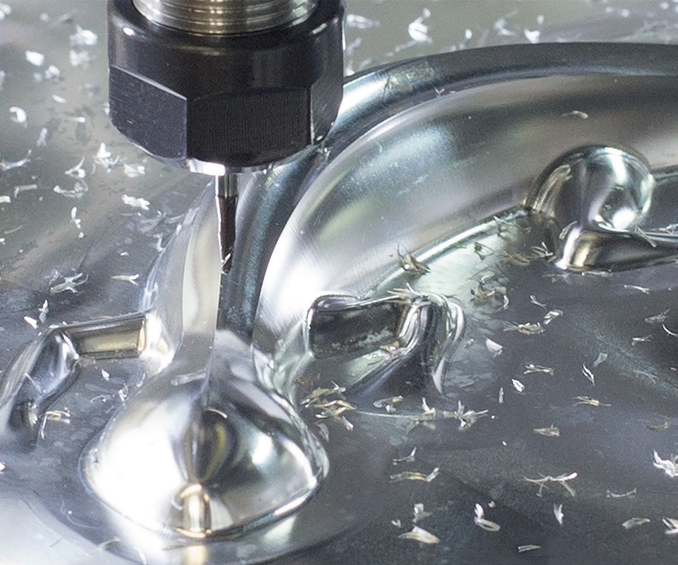
Seen here is the mold surface finish that a CNC motion system’s dynamic precision functions helped to achieve. The mold surface did not require any secondary finishing operations.


In today’s competitive moldmaking marketplace, some mold builders believe the industry’s required tolerances and surface finishes can no longer be achieved with electrodes. Instead, they rely on high-speed cutting of 3D surfaces, which not only meets the necessary tolerance and finish requirements, but can also streamline the manufacturing process and positively impact a shop’s bottom line. This includes the use of five-axis machining, for which the mechanical accuracy and dynamics of the machine are critical, along with the appropriate CAD/CAM, cutting tools, toolholders and workholding systems.
The fast machine motions of five-axis machining, which are true to the contour (meaning the cutting tool/axis motion follows the contour described in the CAD/CAM model as close as possible) require precise control of both acceleration and deceleration along a programmed contour. All of this while keeping machining time, surface quality and geometric accuracy in mind (Figure 1). This can be achieved with a CNC control that uses an approach that is optimized for the milling machine and the manufacturing process. That is, the CNC control has features to either automatically smooth the axis movements or allow the operator to manually set tolerance limits.
At the same time, machine operators must be able to influence the milling results with simple parameter changes. Depending on accuracy and surface quality requirements, the path control of the CNC (which ensures that the machine axes movements follow the programmed path within a predefined tolerance window) directly impacts machining time optimization. That means that, based on the operator or final part priorities, the CNC path can influence the cutting time accuracy or surface finish.
Depending on the application, a shop can get away with using an inexpensive, mainstream CNC solution. However, what many engineers or shop owners do not realize is that when it comes to machining the complex mold surfaces of core and cavity inserts with parting lines and other matching surfaces, shop owners need a sophisticated five-axis CNC motion system. A motion system contains a CNC with a servo-controlled drive system connected to the axis motors and a position measuring system for feedback. Without this, the machine will not be able to reproduce the surface described in the CAD/CAM model.
The recommended system is a closed-loop measuring system, which can master these applications and guarantee a “first time fit” of often previously-hardened mold components (56 HRC or more). A closed-loop measuring system uses a rotation encoder to measure the ball screw rotation, which is then compared to the actual axis position measured by a linear encoder (also known as a glass scale), closing the loop and feeding this information back to the CNC.
Data Processing
Before examining CNC requirements, let’s review how data processing can influence a mold’s accuracy and surface quality. Here are four key influencers of data processing on the results of five-axis mold machining:
1. Non-Uniform Rational B-Splines (NURBS). The CAD-model geometry is transformed into tool paths. Typically, this means the workpiece contour is modeled with NURBS, which makes it possible to mathematically describe free-form surfaces.
2. Computer-Aided Manufacturing (CAM). The tool path elements are calculated point by point under consideration of the milling strategy (what section to rough cut first, how much stock to leave for the finishing cut, etc.), as well as the tool compensation values from the CAD geometry. From there, the predefined model accuracy determines the distance between points.
3. Computer Numerical Control (CNC). The numerical control (NC) program is converted into axis point-to-point movements (machine movements that the CNC control executes) and velocity profiles (speed rates based on part shape or contour). Then preset path tolerances are calculated. This tolerance window determines how close the machine has to move to the actual contour or geometry of the part (Figure 2).
To obtain high-surface definition, the deviations between adjacent milling paths must remain significantly smaller than the defined path tolerances. Basically, the more accurate and consistent the axis movement follows and repeats (moving back and forth in different directions), the better the surface finish and accuracy will be.
4. Mechatronics. The mechanics of the machine and the electronic components that move the mechanical machine components are essential to data processing. For example, the five-axis movements are available in a fixed-time scale (or specified feeds and speeds rates) as nominal, and actual movements are converted over the machine geometry into tool and workpiece movements. This means that you define your movement in the program, but the machine will deviate due to mechanical tolerances from these values. The resulting error of the feed axes, deviations from the machine’s nominal geometry, and machine frame and motor thermal influences and vibrations can reduce the workpiece accuracy.
CNC Requirements
Understanding how data is processed helps to select the appropriate CNC control for a five-axis machine to optimize machining time, surface finish quality and workpiece accuracy. Here are five basic requirements a CNC control should meet:
1. Effective monitoring of contour tolerances. The NC will control the axis movements to follow the 3D surfaces within a predefined tolerance band that are usually created with a CAM system and consist of simple line segments. The CNC should be able to automatically smooth the block transitions while the tool moves continuously on the workpiece surface. An internal function that monitors the contour deviations controls that automatic smoothing. This function enables the user to define the maximum-allowed contour deviation. The default value is defined by the machine tool builder in a machine parameter of the control (typically 0.01 to 0.02 millimeter).
The tolerance also affects the traverse paths on programmed circular motions. This is particularly important if the core or cavity has cylindrical details, which a user machines with either an interpolation milling or a mill-turn function. The latter requires a specific configured machine tool. This newer type of five-axis technology minimizes setup time, improves part detail accuracy and eliminates secondary part setup in a lathe or jig grinding machine.
2. Exact reproduction of adjacent paths after cutting direction reversal. The CNC control should be able to interface with a linear encoder system, ensuring that all machine axes follow the exact path when moving from X-plus to X-minus and then moving from X-minus to X-plus after a step over (Figure 3).
3. Elimination of vibration from highly dynamic movements. A machine axis moving very fast and changing direction on a point or a using a higher-than-permitted feed rate for the cutting tool can generate vibration in the axis, which will impact part quality. The CNC control should be able to monitor any type of tool vibration caused by either high dynamic movements or higher-than-permitted feed rates, and then adjust feeds and speeds to avoid chatter marks on the final part (Figure 4).
4. Flexibility. The CNC control should allow the operator or programmer to verify and optimize the program on-the-fly. Consider, for example, several different mold components made on the same machine. Each part has different accuracy, surface finish and leadtime requirements. Here, the CNC interface should allow the operator to optimize the machine dynamics based on each part’s feature priorities.
5. Automatic feed and speed adjustment. Milling through mold cores or cavities with variable workpiece thicknesses is another machining challenge. A solution is a CNC that can detect how much material is currently cut, so the feeds and speeds can be automatically adjusted without operator intervention. This is accomplished with sensors connected to the CNC that measure spindle load and vibration, and then identify and adjust speeds and feeds within milliseconds. This technology ensures that the machine maximizes chip removal rate, based on workpiece cutting tool engagement, and cutter and spindle life.
6. Five-sided machining in one setup. Not all parts require a full five-axis simultaneous motion. Many mold cores or bases require five-sided machining in one setup. This technique ensures positioning accuracy of features on all five sides of the part, eliminating several setups, and consequently improving the finished part quality. Specifically, this technique improves the tolerances between features on each side of the part. To accomplish this, the machinist wants to program each side of the part in an X-Y-Z plane without changing the CAM program. The CNC should have a spatial plane function that allows the machinist to set the plane that is machined on each side of the part.
Check out this video of a machine tool transforming a sphere into a soccerball, which shows that using a five-axis milling machine with the right control capabilities will allow moldmakers to produce molds and mold components to the right size and finish on the first attempt.


Related Content

Moldmakers Deserve a Total Production Solution
Stability, spindle speed and software are essential consideration for your moldmaking machine tool.
Read More
Developments in High-Speed Machining Technology
There have been many exciting developments in high-speed machining relative to machining centers and controls, tooling and CAD/CAM systems.
Read More
The In's and Out's of Ballbar Calibration
This machine tool diagnostic device allows the detection of errors noticeable only while machine tools are in motion.
Read More
3D Printing Enables Better Coolant Delivery in Milling Operations
Just like 3D printing enabled conformal cooling channels in molds, additive manufacturing is now being used to optimize coolant delivery in cutting tools.
Read MoreRead Next

Examining Mold Surface Quality
High-quality rotary encoders can help improve the quality of milled surfaces.
Read More
Are You a Moldmaker Considering 3D Printing? Consider the 3D Printing Workshop at NPE2024
Presentations will cover 3D printing for mold tooling, material innovation, product development, bridge production and full-scale, high-volume additive manufacturing.
Read More
Reasons to Use Fiber Lasers for Mold Cleaning
Fiber lasers offer a simplicity, speed, control and portability, minimizing mold cleaning risks.
Read More