
FEA of Hot Runners to Optimize Mold Design
Optimization of a mold design with a hot runner system can be done with CAE simulations.


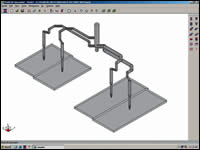
Figure 1: FEA hot runner model. Figures courtesy of Polyshot.
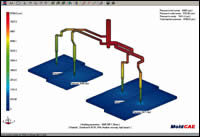
Figure 2: FEA results.
There are many factors to consider when designing a mold. The number of factors increases when adding a hot runner system to the design. When you have all these unknowns, what is the best way to optimize your mold design? Do you design and build the mold and then plan to adjust it after the first sampling? The cost and time needed to do this would not fit into most plans.
Optimization of a mold design with a hot runner system can be done with CAE (computer aided engineering) simulations. Similar to performing a mold flow analysis on a plastic part to enhance its design for injection molding, the same can be done with a FEA (finite element analysis) of a hot runner system.


The results of this analysis, used in conjunction with a hot runner system that can take advantage of those results, will help you finalize the best design for your mold.
The Basics of FEA on Hot Runner Systems
As previously mentioned, performing a FEA of a hot runner system is similar to running a mold flow simulation on an injection molded part. Instead of simulating the flow in the part, the flow in the hot runner system will be simulated (see Figure 1).
First, the initial design of the hot runner system is needed. The design needs to show the number of drops needed, the approximate nozzle locations in the mold and approximate part weight(s). As with any FEA, a CAE model must be generated that represents the hot half design. The flow sizing and distances can be later adjusted based on initial results.
Since this is a FEA of the hot runner system, the plastic parts are simply represented for the analysis. The FEA of the hot runner system should be used in combination with data attained by a part mold flow analysis for more accurate results.
Next, the material properties are chosen from a materials database for the analysis. The final step is inputting the molding parameters that will be used on the tool: mold temperature, melt temperature and holding pressure. With this information in place, the FEA can now be performed.
How to Interpret and Use the Results
Here are some of the results from the simulation that can now be used to optimize the mold design (see Figure 2): pressure drop, temperature change, shear rate, shear stress, runner system volume, part cooling time and clamping force estimation. Using one or a combination of these results will help determine the final and optimal design of a mold.
Number of Nozzles
The pressure drop results can help determine if more drops are needed. If the pressure drop across the nozzle is high, more nozzles should be added to the design to reduce the injection pressure needed to fill the part.
Number of Cavities
For a multi-cavity or family mold, the pressure drop and runner system volume results also can help you decide the appropriate number of drops that will work in the design. Depending on the target for injection pressure, the number of cavities can be increased or decreased based on the pressure drops across the nozzles. If there is an issue of residence time of the material in the manifold, the runner system volume result can be used to calculate the number of shots in the manifold. You may decide to reduce the number of drops in the design if there are too many shots in the manifold.
Nozzle Locations
Once the number of drops has been finalized, you can start reviewing the locations of the drops in the mold. The FEA will then show the fill of the hot runner system and you can visually check if the hot runner system has a balanced fill based on the drop locations. Because the CAE model can be modified easily, moving the nozzles to a different location and then rerunning the FEA will help establish the best locations in the mold design.
Gate Sizing
One of the challenges in designing for a hot runner system is determining the proper starting gate size for the material. The pressure drop, shear rate and shear stress results at the gate will be used to determine the gate size. The gate diameter in the CAE model can be modified until favorable results are achieved.
Design for Varying Materials
Since the initial CAE model can be used to run the analysis independent of material selection, multiple simulations can be performed if different materials are being considered. This can help you optimize wall thicknesses at the gate, gate sizes and request part changes if needed.
Mold Cooling
Mold cycle time is critical for cost savings. The FEA on the hot runner system will calculate the cooling time based on material, mold and melt temperatures. It also will warn you if the cooling time will be too long based on the parameters. Because the FEA does not account for the actual cooling lines in the mold and makes some assumptions that there is minimal cooling for the part, this result will establish if more cooling may be necessary.
Press Tonnage Check
Using the clamping force calculation results is a good check to see if the press the mold was designed for will be adequate. Mold changes should be considered if this is an issue.
Final Thoughts
An optimized mold design is an important part of a program to producing a quality part. With the different types of CAE tools that are available, such as a FEA on hot runner systems, budgets should include the cost to take advantage of these valuable tools. The initial time and cost expense in the design phase will most likely be less than any mold changes required after initial testing and sampling.


Related Content

Products and Services for Multiple Moldmaking Needs
New year, new technology roundup! Featured here is a collection of product offerings, from profile milling cutters to industry-specific CAD/CAM software to innovative hot work tool steels.
Read More
MoldMaking Technology's Most-Viewed Content 2022: Products
MMT shares the five top-viewed technologies, equipment and services of 2022 in each Engineer, Build, Maintain and Manage tenet based on Google Analytics.
Read More
Using CT Scanning to Qualify Molds Faster
Software and hardware advances reduce dimensional inspection with part-to-CAD by 70%.
Read More
Upgrade Your Moldmaking Processes With New Innovations
Read up on new innovations, including modular sorting systems, monitoring platforms for injection molders, indexable milling cutters and more.
Read MoreRead Next

Selecting the Right Gating Method for Your Application
Designers may select among four hot runner gating methods, each with its advantages and disadvantages.
Read More
Understanding the Effect of Pressure in the Cavity
Molders offer a moving target for moldmakers to adjust to by producing parts with different cavity pressures.
Read More
How to Justify Your Hot Runner Purchase
Four questions to help with hot runner justification.
Read More