


Image courtesy of Marposs.
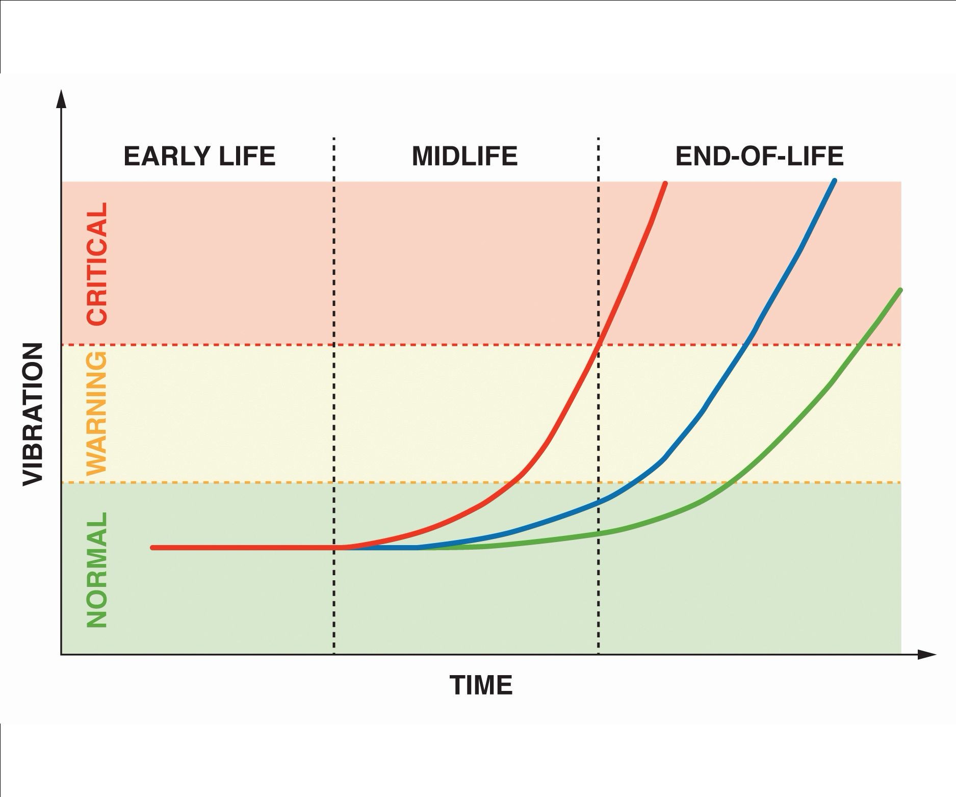
Figure 1. The vibration vs. time relationship for a normal wear mechanism. Figures courtesy of Marposs.
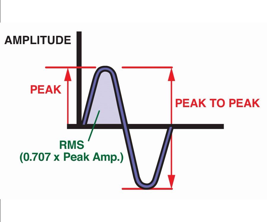
Figure 2. This is a sample signal that is generated by a micro electro-mechanical system (MEMS) or a piezoelectric sensor device.
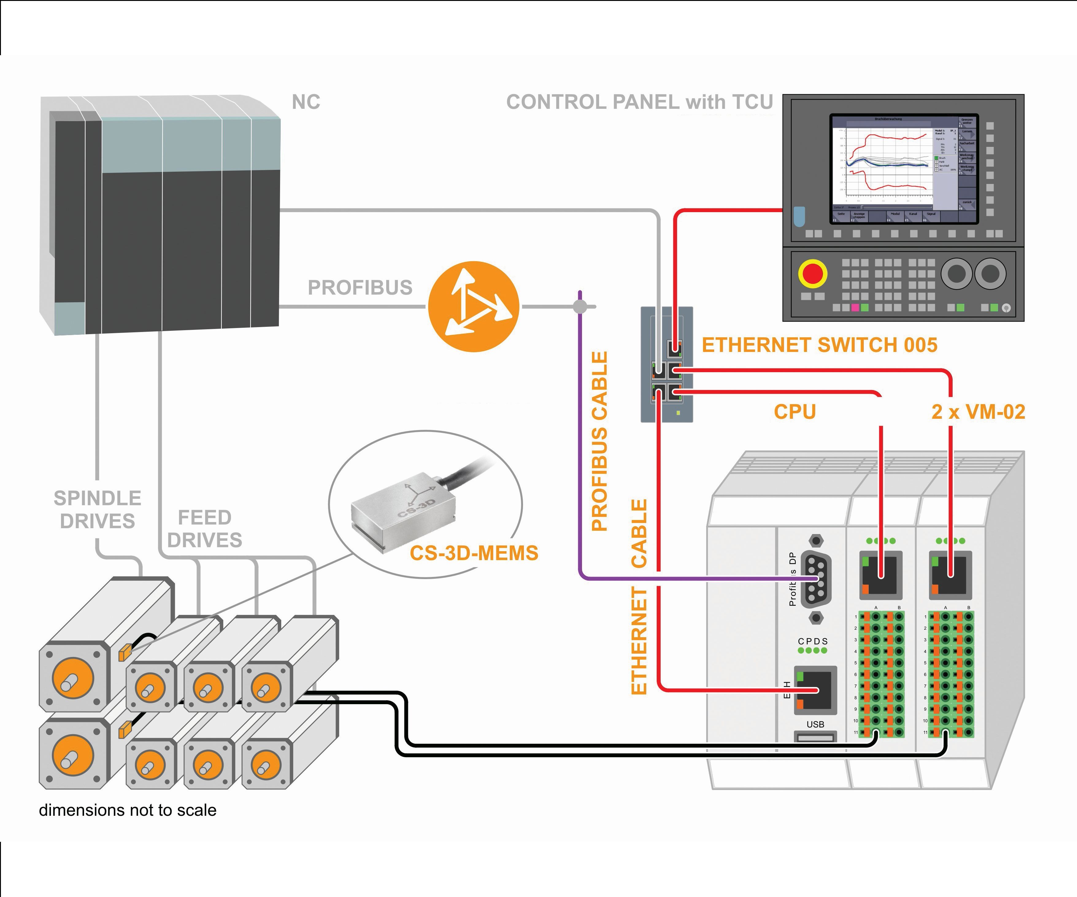
Figure 3. Effective tool condition detection on a multi-spindle head is possible with the right controller, using MEMS vibration-sensing technology in combination with true power monitoring that derives data from seven additional linear axes.
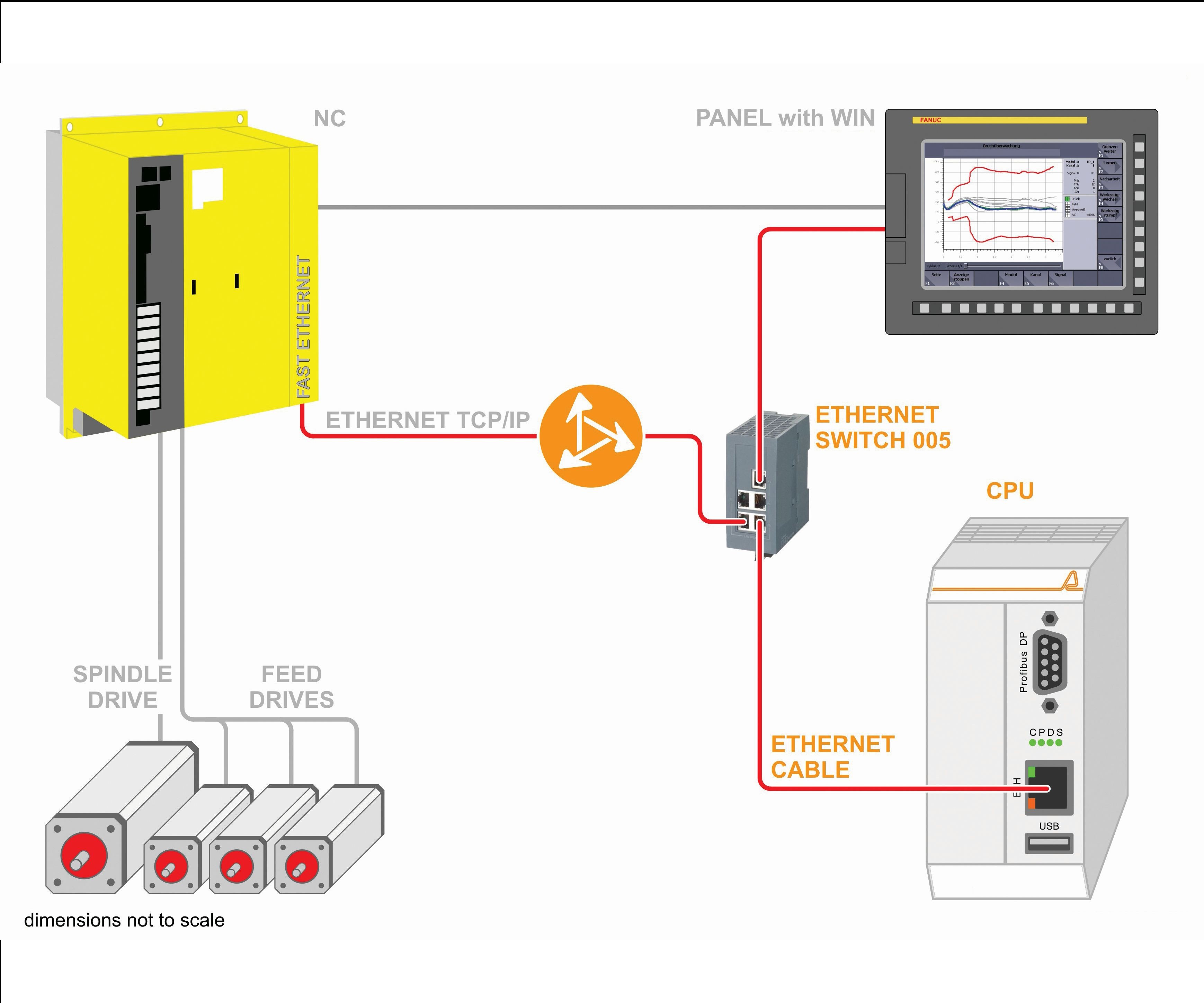
Figure 4. Most of the added components are in the electrical cabinet, simplifying the installation of this control system.


Every shop deals with two universal truths: People are part of the process and make mistakes, and sooner or later, all mechanical devices will either wear out or break. The consequences of both truths can range from merely expensive to catastrophic. A modest investment in machine and process monitoring technology can, and nearly always does, pay large dividends over the long run in sparing moldmakers from the consequences of human error and the breakdown of machines.
Sensors 101


Modern sensor technology comes in one of two forms: micro electro-mechanical systems (MEMS) and piezoelectric devices. Each has a distinct set of capabilities and advantages for machine monitoring applications.
MEMS sensors are miniature machines with integrated electronics that are produced by technologies similar to those used in the manufacturing of semiconductor devices. Because MEMS sensors are highly reliable and are relatively inexpensive, they are widely used in all sorts of electronic devices where their small size, low consumption of power, ease of integration, high level of functionality and superb performance encourage and enable innovation.
Because MEMS sensors are highly reliable and are relatively inexpensive, they are widely used in all sorts of electronic devices where their small size, low consumption of power, ease of integration, high level of functionality and superb performance encourage and enable innovation.
The major advantage of a MEMS sensor in a machine-monitoring application is its ability to detect vibration at extremely low amplitudes. For example, a MEMS sensor can detect vibration in a spindle rotating at speeds as low as 2 rpm. Because the signal processing electronics are integrated into a MEMS sensor, MEMS sensors also tend to be less expensive than comparable piezoelectric units.
Piezoelectric sensors use the current that is generated by deforming a crystal to measure the amplitude of a vibration. Piezoelectric sensors are not able to detect low amplitude vibrations nearly as well as MEMS devices. They deliver a non-linear response in that region. However, piezoelectric sensors are extremely rugged and are able to survive crashes generating up to -70 Gs, while most MEMS sensors experience damage at about -18 Gs.
A further advantage of piezoelectric sensors is their ability to respond to vibration and acceleration in three axes instead of one or two for MEMS devices. The combination of ruggedness, 3D sensing, and the ability to serve as both a vibration and crash detection device make piezoelectric sensors the technology of choice for most large machine tools.
Vibration Analysis
While acceleration sensing is the key to crash protection, vibration detection provides the critical inputs for machine-condition monitoring. Every component of a machine tool generates a characteristic vibration profile, which changes predictably over time as it experiences normal wear. By periodically measuring the vibration profile and comparing the data over time, one can track component condition and predict the onset of imminent failure.
Figure 1 shows three examples of the vibration-versus-time relationship for a normal wear mechanism. Although it takes time and experience to develop this type of relationship, a well-correlated vibration signature can be a cost-saving alternative to regular maintenance performed at short cycle times. Using actual vibration observations provides an opportunity to take quick action when warning conditions are detected (red curve), while avoiding premature maintenance on machines that have more life remaining (blue and green curves).
While acceleration sensing is the key to crash protection, vibration detection provides the critical inputs for machine-condition monitoring.
A typical application for this technology is placing a sensor on the main bearing casting of a machine tool spindle, since the main bearing is the most common point of failure. The signal that the sensor generates will look something like the idealized trace in Figure 2. It is analyzed using the ISO standard procedure for determining the root mean square (RMS) value of the area under one half of the trace. This provides more useful data than merely measuring the peak-to-peak value and is the procedure used in the algorithms in most monitoring software.
Fourier analysis is another standardized procedure used to normalize vibration data. Fourier analysis represents functions as a sum of simpler trigonometric functions. A fast fourier transform (FFT) changes vibration data based on time values to frequency values. It is useful for preventive maintenance applications because wear tends to increase both amplitude and frequency, which may not be obvious when comparing time-domained signals.
Other Monitoring Technologies
Acceleration detection and vibration analysis technologies are the foundation of any practical machine-monitoring application, but they are by no means the only tools available. Anyone machining high-value workpieces on expensive high-precision machine tools ought to seriously consider moving beyond the basics to a more comprehensive suite of technologies. The best place to start is probably with a true power monitoring application that measures the actual energy consumption of a motor. Current alone is an unreliable measure of motor performance. A combination of current, voltage and the phase difference between them enables a machinist to accurately calculate true power consumption.
The most common application of true power monitoring is on the spindle motor of a machining center. On a large machine, however, this may not be sufficient to provide the necessary protection. Consider, for example, the difference in power consumption between a 4-inch diameter face mill and a 5-millimeter drill on a 50kW spindle. For all practical purposes, the drill will be invisible even to the best true power technology. The answer is to apply true power technology to the axis drive that feeds the drill. That motor will be much smaller, and measuring its power consumption will provide tool condition data and breakage protection on the drill.
The most common application of true power monitoring is on the spindle motor of a machining center.
It is also possible to instrument individual toolholders with strain gauge technology. Unlike piezoelectric sensors, strain gauges can be loaded for extended periods of time without drifting. This makes them an excellent solution for gun drilling and tapping applications. For example, there are toolholder-mounted strain gauge units capable of tracing the entire profile of a tapping operation at speeds up to 27,000 rpm. True power monitoring is not effective in such an application because most of the power that is supplied to the motor is actually consumed in the motor under those conditions, making it extremely difficult to differentiate the power that is consumed by the tap.
Multi-spindle heads are another specialized situation that often require different monitoring technologies. In practical terms, true power monitoring of the spindle motor can be effective in detecting tool condition or breakage on a multi-spindle head using up to four identical tools (see Figure 3). Anything beyond that will probably require an alternative technology. In those cases, acoustic monitoring is the most common choice. As long as the tool diameter does not vary by more than 20 percent, an acoustic monitor can detect breakage in a multi-spindle head with many more than four tools. If the diameter varies by more than 20 percent, multiple monitors may be necessary.
It is possible to monitor motor torque without using sensors on machines by using several specific controllers. Digital torque adapter technology uses a proprietary interface to collect data directly from the control central processing unit (CPU) and processes it to generate graphic torque values. The system, which is commonly used in Europe, can monitor multiple axes and deliver all the functionality of a sensor-based system.
It is possible to monitor motor torque without using sensors on machines by using several specific controllers.
Putting Monitoring to Work
Modern machine and process monitoring technology is as easy to implement as a retrofit solution. For example, installing a true power monitor on a vertical machining center typically takes no more than two to three hours, plus the time needed to program the PLC. A complete crash protection, vibration sensing and tool condition monitoring system might take eight hours to install on the same machine. Figure 4 shows a generic layout for a comparable system on a machine tool. Since most of the added components are in the electrical cabinet, the actual installation of the control system is quite simple. The digital torque adapter installation is even simpler.
As long as people make mistakes and machines wear out, some form of crash protection and condition monitoring technology will be the first line of defense against expensive and potentially catastrophic consequences. Fortunately, the technology is mature, effective, affordable and easy to implement, so there is no point in waiting to put it to work.
About the Contributor
Jorge Peña-Mena
Jorge Peña-Mena is the general manager and director of Application Engineering for Artis Systems Inc. and Marposs Corp.


Related Content

CT Scanning Helps Micro Molder Reduce Cost of First Article Inspections
CT scanning services performed by 3D ProScan, a division of NyproMold Inc. provides MTD Micro Molding with accurate, high-resolution internal and external measurements performed about seven times faster and at significant cost savings.
Read More
IMTS Showcases Software, Additive Manufacturing, Inspection and Measurement Tools for Moldmakers
MoldMaking Technology previews a selection of the software, additive manufacturing, inspection and measurement tools that will be present at IMTS.
Read More
Products and Services for Multiple Moldmaking Needs
New year, new technology roundup! Featured here is a collection of product offerings, from profile milling cutters to industry-specific CAD/CAM software to innovative hot work tool steels.
Read More
Technology Roundup: New/Improved Technologies You Don't Want to Miss
With all the technology joining the market, moldmaking is a versatile, ever-evolving industry. As such, this technology roundup has no specific theme — it features a variety of products for applications and solutions across the industry.
Read MoreRead Next

Why You Need a Tool Presetter
Reduce machine idle time with fast, accurate, repeatable, offline cutting tool measurements.
Read More
Are You a Moldmaker Considering 3D Printing? Consider the 3D Printing Workshop at NPE2024
Presentations will cover 3D printing for mold tooling, material innovation, product development, bridge production and full-scale, high-volume additive manufacturing.
Read More
How to Use Continuing Education to Remain Competitive in Moldmaking
Continued training helps moldmakers make tooling decisions and properly use the latest cutting tool to efficiently machine high-quality molds.
Read More