
Eliminate Multiple Toolpaths With Interleaving Technique
Intelligently applying the right style of toolpath in the right place in a single pass is achieved with an interleaving technique.


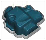
Figure 1: The CAM system calculates whether spiraling passes are needed, how many, and at what tangency angle to achieve a constant scallop height over the entire part.
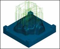
Figure 3: Combined horizontal and vertical machining passes require more tool retractions and more duplication of effort.
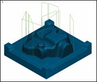
Figure 2: Z-level machining. Note the shallow areas the toolpath skips and the multiple retract moves as the tool repositions between passes.
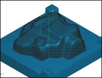
Figure 4: The interleaved spiral toolpath is more efficient, produces a more consistent surface finish over the entire part and dramatically reduces retract moves.
Complex surface machining has always presented a challenge to moldmakers. The types of toolpaths that work best on vertical and near-vertical surfaces are quite different than the toolpaths preferred for horizontal and near-horizontal surfaces. The decisions about which types of toolpaths to use and exactly where to apply them are left to the CNC programmer, who bases these decisions on a combination of experience and guesswork as to what will produce the best surface finish on the final part.
The Traditional Approach to Surface Machining
With traditional CAM programming, toolpaths that approach the part from the side (usually a constant z-level slice) are typically used for vertical and near-vertical surfaces while toolpaths that approach the part from above (typically a projection milling technique) are applied to horizontal and near-horizontal surfaces. There also are toolpaths that follow the mathematical ISO lines of each surface. With multisurfaced parts, each of those surfaces has its own set of ISO lines—meaning the tool has to pick up and go to a new set of ISO lines between each and every surface. That’s a lot of retractions.


A moldmaker may choose any combination of these toolpaths to cut the entire part as a whole. Some of the problems with this approach are:
A Better Solution
CAM systems that have intelligent machining capabilities solve these problems with a new type of toolpath that uses a single-pass technique to intelligently apply the appropriate combination of z-level and projection cutting passes based on the shape of the part.
The interleaved spiral toolpath is based on a z-level slicing technique that steps the tool down at a constant Z increment through the entire part. The CAM system first analyzes the slope and shape of part surfaces and then uses a scallop height constraint to calculate whether spiraling passes are needed between Z levels. While the tool is still on the material at the end of each z-level slice, it moves around to any shallow areas that would be missed by the next z-level slice and interleaves spiral cutting passes to remove this material before moving on to the next z-level slice. Continuous cutting passes are created that match the shape of the part with minimal, if any, tool retractions.
The user simply specifies the maximum slope value for areas where interleaving should take place and the maximum scallop height to achieve the desired surface finish. The CAM system calculates whether spiraling passes are needed, how many, and at what tangency angle to achieve a constant scallop height over the entire part (see Figure 1).
The interleaved spiral toolpath produces:
- The most effective toolpath based directly on the shape of the part
- A consistent step over and a smooth finish all the way around the entire part regardless of the slope angle of the surfaces
- A limited number of retract moves
- A single toolpath that reduces programming time
Let’s Compare
A z-level cutting routine creates toolpaths as the tool steps down through the part at constant Z increments. This is a quick way to produce toolpath, but on complex surfaces it leaves an undesirable surface finish on non-vertical surfaces and can completely skip shallow areas unless the step in Z is set to an incredibly small value (see Figure 2).
In order to effectively machine horizontal and near-horizontal areas, the CNC programmer must create additional projection toolpaths in addition to the Z-level cutting passes. This not only adds another step to the process, but increases the number of retract moves and creates duplicate machining passes in some areas. This is an extremely inefficient way to program your parts (see Figure 3).
The interleaved spiral toolpath analyzes the shape of complex surfaces to intelligently apply the most appropriate toolpath as the tool moves across the entire part (see Figure 4).
Thinking Ahead
The ability to accurately machine complex surfaces is critical to the success of moldmakers. CAM software developers who understand this need play an important role by providing machining strategies that not only produce a superb surface finish but also save the moldmaker time and money. CAM systems that build intelligence into the product not only solve the problems faced by moldmakers today, they anticipate the needs of tomorrow.


Related Content


Precision Welding Services Offer Rapid Turnaround Mold Repair and Reduced Molder Downtime
X-Cell Tool & Mold relies on outsourced, high-quality welding repairs from Lewis-Bawol Welding to ensure its customers' molds are back in production quickly and affordably.
Read More
Questions and Considerations Before Sending Your Mold Out for Service
Communication is essential for proper polishing, hot runner manifold cleaning, mold repair, laser engraving and laser welding services.
Read More
Laser Welding Versus Micro Welding
The latest battle in finely detailed restoration/repair of mold materials.
Read MoreRead Next

Choosing the Right Knowledge-Based CAD/CAM System
CAD/CAM systems that offer knowledge-based machining deliver tremendous savings in both time and costs, but only when the system meets your specific needs.
Read More
How to Use Strategic Planning Tools, Data to Manage the Human Side of Business
Q&A with Marion Wells, MMT EAB member and founder of Human Asset Management.
Read More
How to Use Continuing Education to Remain Competitive in Moldmaking
Continued training helps moldmakers make tooling decisions and properly use the latest cutting tool to efficiently machine high-quality molds.
Read More