Does Your CAD System Support Design and Validation In One Window?
Implementing one tool that can handle part design, mold design, part structural analysis and mold filling analysis is becoming a necessity for today’s mold shops.


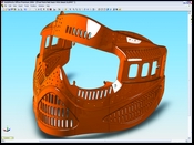
Figure 2. Both product designers and moldmakers need software that can handle complex geometry.
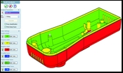
Figure 5. Multi-color draft analysis lets you see the degree to which different surfaces are drafted.
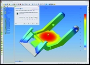
Figure 6. Integrated mold filling simulation allows faster analysis iterations and puts the power of analysis in the designers’ hands.
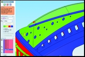
Figure 3. Real-time diagnostics of parting line completeness aids in parting line development.
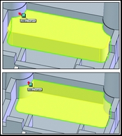
Figure 4. The ability to automatically toggle through different steel-to-steel shutoff solutions simplifies and speeds up parting surface creation.
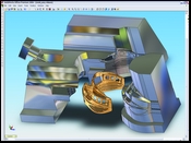
Figure 1. Paintball mask and mold designed and validated in one system. Figures courtesy of SolidWorks Corporation.
Whether designing the mold for an iPod or a refrigerator door, moldmakers are always looking for faster methods to help them produce molds. One thing they would like to avoid is the need to constantly export, import and repair data between design and validation. For plastic part designers and mold-makers this is especially true. In this industry there is much overlap between disciplines: product design, product validation, mold design and mold validation—where does one job stop and the other begin? Having a tool that can handle part design, mold design, part structural analysis as well as mold filling analysis is becoming a necessity to getting the job done on time (see Figure 1).
The process of translating data between disparate software tools, long an industry standard, takes time and increases the risk of errors. It also widens the communications gap between product designers and moldmakers. By providing product design, mold design and validation tools directly in one package, the communication gap between designers and moldmakers is bridged and the product development cycle can be accelerated.


Over recent years, plastic part designers and moldmakers have primarily focused their efforts to improve the design of products and molds in two areas: 3-D solid CAD software and simulation software for validating part and mold designs upfront before tooling is cut. While moldmakers have made great strides in implementing 3-D mold design and analysis tools, far fewer have established an environment to take advantage of the integration of design and validation. In other words, design and validation are still seen as separate environments and the models are still “thrown over the fence” from one package to another.
In most cases, the inability to integrate is based on the fact that these software packages do not share a common file format, thus translation of data is required between these systems. A separation of duties based on software occurs, which affects a company’s ability to design products and molds concurrently.
When product design and validation software is seamlessly integrated, users can move easily back and forth between these disciplines. Since the user doesn’t have to translate the geometry, they save time, they know they are working on the most current and accurate version of the model, and they can work concurrently with their colleagues—there is no more “fence” to throw their designs over.
3-D CAD Checklist for Design and Validation in One Window
The advantages of having product design/validation and mold design/validation in one package are clear. Now the question is: “Does my 3-D CAD system support all of this in one package?” There are some fine details to pay attention to here.
Functionality Check
First start by checking the functionality provided in your current 3-D CAD package. What is part of your basic package—functions for advanced modeling, mold design, part structural analysis and mold filling simulation?
Ability to Support Concurrent Design Environment
In order for the 3-D CAD system to support concurrent design and validation, the system must be both parametric and associative. Parametric means that a user can select a dimension, or some other defining characteristic, to modify the model. Other features of the model will then update appropriately based on this change. Associative means that a change made to the part model will automatically show up everywhere else where that part is used. For example, a change made to the part will affect the assembly, the drawing, the mold or even an electrode that is related to this part.
Product and Mold Design Details
Power to Handle Complex Geometry
For the software to be usable for plastic part design, it must be powerful enough to handle the complex geometry. The system must possess round, draft and complex surfacing capabilities. The ability to sweep and loft surfaces and solids are typically necessary (see Figure 2).
Import, Diagnose and Repair Geometry
Unfortunately, we can’t get away from this. Inevitably you will get files from customers or suppliers that will be in a format not native to the 3-D CAD system you are using. Modeling often begins with importing the model and then diagnosing and repairing it. Look for systems that include tools to run import diagnostics and even automatically repair and zip gaps in surfaces. Most times, you will have to do some manual repair, so look for tools that make this easier. For example, some tools offer feature recognition for imported geometry, the ability to automatically select and remove rounds and the ability to automatically re-trim the edges once the rounds have been removed. This is especially helpful to mold designers who must add draft to a customer part that already has rounds and is drafted improperly.
Specialized Mold Design Functions
Mold design typically follows a series of steps, and there are particular features and functions that mold designers look for to get their jobs done faster. Besides importing and repairing data, and modeling complex geometry, mold designers need other specialized mold design functions such as parting lines, parting surfaces and splitting that are unique to mold design. Let’s look at these specialized functions in more detail.
Create the Mold Parting Line
The parting line is the foundation for all other mold geometry to follow. Although many parting lines can be determined by eye, there are many situations in which the parting line is not as obvious. Systems that can create parting lines automatically typically perform a draft analysis based on user-defined pull direction by finding the boundary between positive and negative draft. Unfortunately, this does not always give you the solution you want. Often the draft on the part is not correct or there are multiple possible draft solutions. Some systems allow manual interactions in the automated mode, which allow the moldmaker to apply his own skills for questionable areas, and even get feedback as to whether the parting line is complete or not (see Figure 3).
Create the Mold Shutoff Surfaces
Steel-to-steel shutoffs are some of the toughest geometry to model in a mold. Look for software that allows automatic and interactive shutoff surface creation. The ability to toggle through shutoff surfaces that are created automatically by the system significantly speeds up parting surface creation (see Figure 4).
Create the Mold Parting Surface
The main parting surface is usually based on the parting line. Again, as with parting lines and shutoff surfaces, automated functionality with the ability for the user to manually interact is best. Areas where surfaces cannot be created automatically, or where the automated surface creation is unacceptable, require surfaces to be created manually. Organization of parting surfaces is important. Look for software that allows you to create “folders” to help organize and keep track of parting surfaces.
Split the Mold
Now that the appropriate surfaces have been created—including shutoff and main parting surfaces—the system should be able to automatically calculate how to split the mold block into solid geometry.
Add Geometry to Handle Undercuts (Slides, Lifters and Cores)
Before modeling any inserts, cores or pins, an undercut analysis (see next section) should be performed on the core and cavity blocks to determine if any side cores or lifters are required. The creation of core geometry is usually achieved by sketching the outline of the core on an appropriate planar face or plane. This is then extruded through the mold block cutting out a solid. The user should be able to add draft in the pull direction for a side core by including it in their sketch of the core profile. In some CAD software, draft in the retract direction for the side core is handled automatically by the system with an ability to input an appropriate draft angle.
Product and Mold Analysis Details
Compare Part for Changes
When the design model changes, you need to know what changed. Look for tools that make it easy to detect what is different in a part; tools that help you to graphically visualize what geometry has been added or subtracted in the parts are recommended.
Draft Analysis
Draft analysis is really the first step to finding out if a part is drafted properly so it can eject cleanly from the mold. Look for the ability to represent amount of draft graphically, with color. You also can use draft analysis to verify your mold inserts (see Figure 5).
Undercut Analysis
Undercut analysis is different than draft analysis in that it shows areas in which geometry would be captive. These areas will typically require sliders, lifters or cores.
Thickness Analysis
Another tool that is handy for part and mold designers is the ability to check thickness of a part. This helps to avoid areas that are too thick and may sink, or areas that are too thin.
Structural Analysis
The ability to simulate linear and nonlinear material behaviors—including that of plastics, rubber and metals without having to export to another system—allows the user to quickly investigate many design scenarios to optimize part and mold designs. By using these tools you can determine the life cycle of a part or mold design and predict the failure of structures under cyclical loading.
Mold Filling Simulation
Mold filling simulation software validates whether a plastic injection-molded part can be molded. The integration of these products directly into the design software lets the designer or moldmaker quickly check to see if the design will fill. Problems with filling can be caught immediately, before tooling is cut; corrections can be made and the analysis re-run within a matter of minutes without ever having to export the design model. In addition, injection locations can be determined and part wall thicknesses can be optimized (see Figure 6).
Summary
If you are currently looking for a new 3-D CAD system, think before you buy. Ask yourself if the system allows seamless integration of design and validation, thereby eliminating the need to export data. Does it provide all of the functionality and power that you need to get the job done? Is it easy to use and learn—users will tend to fall back on the old systems if the new systems are too difficult to use. And finally, is there a support network available if you are having problems?
By using 3-D CAD software that combines design and validation in one system, designers and moldmakers can work more productively and reduce costly errors. By integrating these applications within the same 3-D CAD tool, the imaginary “fence” known as data translation—which has stood as a barrier between designers and moldmakers—is eliminated.


Related Content

Mold Builder Uses Counter-Intuitive Approach for Mold Challenges
Matrix Tool Inc. answers customers’ hard questions with creative solutions for cavity spacing, tool sizing, runner layout and melt delivery that reveal the benefits of running in a smaller press size at lower cavitation but higher yield.
Read More
MMT Chats: Marketing’s Impact on Mold Manufacturing
Kelly Kasner, Director of Sales and Marketing for Michiana Global Mold (MGM) talks about the benefits her marketing and advertising, MGM’s China partnership and the next-generation skills gap. This episode is brought to you by ISCAR with New Ideas for Machining Intelligently.
Read More
Editorial Guidelines: Editorial Advisory Board
The Editorial Advisory Board of MoldMaking Technology is made up of authorities with expertise within their respective business, industry, technology and profession. Their role is to advise on timely issues, trends, advances in the field, offer editorial thought and direction, review and comment on specific articles and generally act as a sounding board and a conscience for the publication.
Read More
OEE Monitoring System Addresses Root Cause of Machine Downtime
Unique sensor and patent-pending algorithm of the Amper machine analytics system measures current draw to quickly and inexpensively inform manufacturers which machines are down and why.
Read MoreRead Next

Moving Mold Design From 2-D to 3-D
Moving to 3-D mold design can provide a very effective way of improving competitiveness and helping companies win more business.
Read More
Simulate and Optimize Your Mold Build Process
Mold shops can increase efficiency, lengthen tool and machine life and achieve better surface finish with the same software they use to verify their increasingly complex NC programs.
Read More
How to Use Strategic Planning Tools, Data to Manage the Human Side of Business
Q&A with Marion Wells, MMT EAB member and founder of Human Asset Management.
Read More