
Designing Plastic Components and Injection Molds for Robotically Dispensed Foam-in-Place Gasketing
While robotic technology improves design flexibility and productivity, up-front attention to component and mold design can lead to even higher gains


Stay on the Straight, But Not the Narrow

Practice Tolerance
No Knives Allowed
A Smooth Surface for Smooth Sailing
Don't Be Square

A Clear Path Is a Good Path

Stay Mainly on the Plane
Robotic foam-in-place gasketing (FIPG) is an established technology for automating the gasketing of component parts used in the manufacture of plastic automotive, appliance and electrical components. Many plastic parts are amenable to the use of foam-in-place gaskets. However, up-front attention to mold and plastic part design is critical to capture the high productivity and superior performance of FIP gasket technology.
Some applications include vacuum cleaners, air filters, dishwashers, clothes dryers, dehumidifiers, air conditioners, freezers, refrigerators, ranges, air cleaners and computers. The potential benefits of the foam-in-place gasket approach are a significant reduction in labor costs, increased flexibility in both product and process design and seamless, high-performance gaskets.


The purpose of this article is to explore issues of part design that yield higher manufacturing productivity and improved gasket performance from the use of foam-in-place gaskets. First, though, a few words about the FIPG process.
The FIPG Process
An FIPG foam is a void-filled polymer matrix. The foam is applied robotically to a part as a liquid or semi-liquid and cures to a solid on the part. Foams can be one-component, such as hot melt or urethane moisture cure; or two components, such as polyurethane or silicone. One-component foams are produced by mechanically mixing an inert gas - such as nitrogen - into the material, while two-component foams are produced by the production of gas in a water-based side reaction, as the material is blended during the dispensing process. Selection of the foam material depends on the application and the gasket performance specifications. However, two-component polyurethane foams are most widely used in the FIPG process since they offer the widest range of physical properties.
The viscosity of different FIPG materials can vary widely, from a paint-like consistency to a thick paste (thixotropic). The way in which these materials flow onto a flat surface or into a groove has implications for part design.
For both one- and two-component foams, the liquid - or semi-liquid - material must be applied to the substrate very accurately since curing will occur wherever the material is first laid down. The material cannot be adjusted or moved into position after the fact. For this reason, the material is almost always robotically applied. While round parts can sometimes be gasketed with a simple turntable, most applications require either a three- or six-axis robot. It is the robotic's requirement that actually leads to some of the major benefits of FIPG, which are a reduction of labor and an increase in placement accuracy. So, robotic application also influences part design.
Fixturing is another important aspect of the FIPG process. Parts must be moved into and out of the dispense station accurately and quickly in order to ensure high productivity, and they must be presented to the robot in an optimal fashion. These factors also impact part design.
Optimal Part Design
Since FIPG materials can be applied either in a groove (liquid) or on a flat surface (semi-liquid paste), most component parts can be converted from manual gasketing to foam-in-place. However, a part that is designed with the FIPG approach in mind will lead to both higher production efficiency and optimal gasket performance. Following are part design guidelines that help to achieve both of these objectives.
Stay Mainly on the Plane
While sloped regions as steep as 45 degrees can be accommodated, the gasket should be dispensed onto as consistently horizontal a surface as possible. This will simplify the robotic requirements and reduce any potential slumping of the dispensed material. (A sloped application requires a thixotropic FIPG material to avoid slumping.) The part should also be designed so that it sits flat. This will ensure that the material remains level during and immediately after foaming, thereby avoiding additional table fixture costs.
Get in the Groove
Whenever possible, a groove should be designed into the part to accept the gasket. A groove will allow the use of lower viscosity liquid materials, which will self-level and avoid a visible "knit line" - the point where the end of the gasket rejoins the beginning. A groove also protects the gasket from wear and abuse. The groove walls should be continuous and equal in height at all points so that the resulting gasket is uniform.
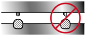
Stay on the Straight, But Not the Narrow
Narrow groove width is probably the most common design error. Material will not flow easily into a narrow groove, and air entrapment can occur. Also, the dispense nozzle must have a small inside diameter, which leads to a low flow rate and, thus, low robot speed. The overall result is a longer dispense cycle time. Production rates can be significantly increased by use of an appropriate groove width. While groove widths as small as 1/8" can be gasketed, the groove should preferably be from 3/16" to 3/4" wide. Also, the groove width should be uniform around the part so that a constant robot speed and dispense rate can be maintained. This will lead to a gasket of uniform height.
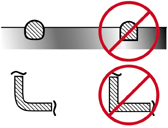
Don't Be Square
Corners - both for flat and grooved parts - should be rounded so that the robot can maintain speed in the turns. The bottom of a groove should also be rounded so that air is not entrapped while material flows into the groove. These design features lead to higher robot speed and increased production rates.
Practice Tolerance
The gasket should be compressed between 35 to 45 percent to ensure proper sealing. Make sure that the tolerance between the mating surfaces is not a significant fraction of the gasket height. For example, if the tolerance between the parts is +/- 0.030" (so 0.060" = 10 percent variation), the overall height of the gasket should be 0.600". Obviously, you want the least part warpage as possible to occur.
No Knives Allowed
Mating surfaces should have a radius edge or flange rather than a knife edge to minimize the chance of cutting the gasket surface when under compression.
Stick to Your Reliefs
FIPG materials do not adhere well to polyethylene, polypropylene, stainless steel, galvanized steel or aluminum. These plastic substrates require either a groove or surface pre-treatment, while the metals might require either a groove or priming.
A Clear Path Is a Good Path
Component parts should be free of obstacles such as posts or flanges that impede the movement of the robot or mix head.
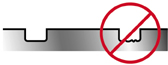
A Smooth Surface for Smooth Sailing
The gasket surface should be free of rough surfaces created in the injection molding process such as knock-out marks or gussets. This reduces the chance of air entrapment that can lead to bubbles in the gasket surface and compromise the integrity of the seal.
Summary
The FIPG process is a proven and cost-effective approach to gasketing many existing appliance parts. However, optimal productivity and gasket performance is best achieved by considering FIPG issues during the initial component design process.


Related Content

How to Eliminate Chatter
Here are techniques commonly used to combat chatter and guidelines to establish a foundation for optimizing the moldmaking process.
Read More
Hands-on Workshop Teaches Mold Maintenance Process
Intensive workshop teaches the process of mold maintenance to help put an end to the firefighting culture of many toolrooms.
Read More
Treatment and Disposal of Used Metalworking Fluids
With greater emphasis on fluid longevity and fluid recycling, it is important to remember that water-based metalworking fluids are “consumable” and have a finite life.
Read More
Forces and Calculations Are Key to Sizing Core Pull Hydraulic Cylinders
To select the correct cylinder, consider both set and pull stroke positions and then calculate forces.
Read MoreRead Next

How to Use Continuing Education to Remain Competitive in Moldmaking
Continued training helps moldmakers make tooling decisions and properly use the latest cutting tool to efficiently machine high-quality molds.
Read More
How to Use Strategic Planning Tools, Data to Manage the Human Side of Business
Q&A with Marion Wells, MMT EAB member and founder of Human Asset Management.
Read More
Are You a Moldmaker Considering 3D Printing? Consider the 3D Printing Workshop at NPE2024
Presentations will cover 3D printing for mold tooling, material innovation, product development, bridge production and full-scale, high-volume additive manufacturing.
Read More