
Designing Flow Leaders and Restrictors
Use simulation to control flow in your injection molds.
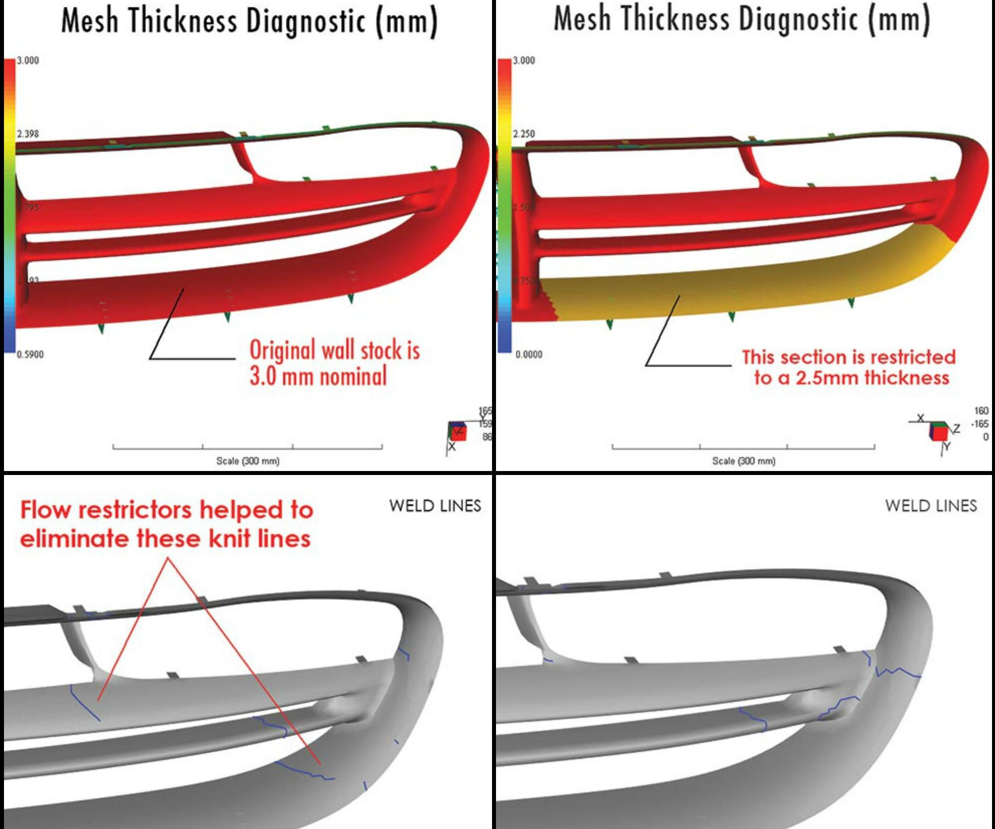
Figure 1 - Before and after adding flow restrictors to a front grille. Using restrictors helps push visible knit lines into less conspicuous areas. Figures courtesy of CAE Services.
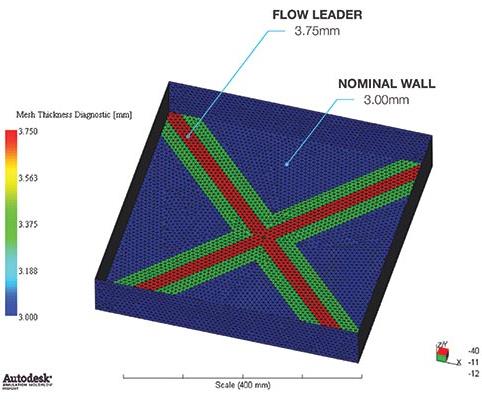
Figure 2 - A typical flow leader pattern added to a simulation model for a computer housing.
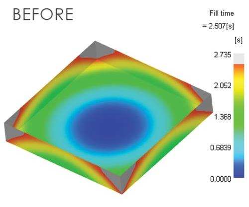
Figure 3 - Filling patterns before and after adding flow leaders. Flow leaders help to promote more plastic flow to the corners to provide balanced filling and packing, and reduced warpage.
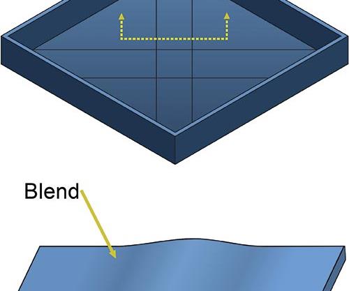
Figure 4 - Blending flow leaders back to the nominal wall is important to avoid abrupt changes to the surface appearance on the opposite side.


Nearly 25 years ago, before I started doing flow simulation at CAE Services, I worked through graduate school as a designer building CAD models of injection-molded plastic parts for a well-known printer company. I did not know much about designing for plastics then, because my physics and mechanical engineering courses covered metals. What I learned about plastics was through on-the-job training.
I was fascinated by the differences in designing for plastics. The engineers who designed the parts would often send me changes to incorporate into the CAD model. The reasons for the revisions were usually obvious, and mostly for part form and function. Other times, however, the reasons were not so obvious. I gradually learned that, in these cases, a design change was needed to improve part manufacturability.


For example, I was working on a housing for a computer dumb terminal, which was essentially a flat, horizontal box about 18" × 18" × 3" with a bunch of ribs and screw bosses on the inside that were mounting points for the motherboard. The part was molded from PC/ABS and was center-gated with a single cold sprue gate. When the first samples were molded, they came out like potato chips, warping upward in two opposite corners and downward in the other two corners. After consulting with one of the materials experts, the engineer showed me some hump-shaped features that he wanted me to incorporate into the model.
These humps resembled speed bumps extending from the center gate to each of the four corners of the part. I made the changes to the CAD model, but wondered why those features could possibly be needed in the part. The changes were passed along to the moldmaker, and the parts came out very flat in the next mold trial.
Another example involved the front grille of a car. There were only so many locations gates could be placed and only so many ways to sequence the valve gates to change the filling pattern. None of the gating/sequencing combinations produced acceptable knit lines for this highly aesthetic piece requiring less visible locations. The last option required adding wall stock in some select locations and reducing it in other locations to produce the desired knit line locations (see Figure 1).
Flow Leaders and Restrictors
These two examples illustrate flow leader and flow restrictor uses. A flow leader is a local increase in wall stock to promote plastic flow, while a flow restrictor is a local reduction in wall stock to inhibit flow. Used correctly, flow leaders and restrictors can improve the quality of molded parts when conventional means cannot.
As a moldmaker, you need to create a mold that is cut to very tight tolerances and that produces good parts with a robust processing window. However, limitations in part design, gating choices and mold design can make this very difficult, as the aforementioned examples illustrate.
So, when you have attempted everything possible from a processing standpoint and are still getting bad parts, it may be time to add a flow leader to the process. But how should this flow leader be designed? Three approaches come to mind (in order of least-preferred to most-preferred):
• Design at the press. Steel is hogged out of the mold’s B side as it is hanging in the machine during the mold trial.
• Design by the moldmaker. The mold is returned to the shop to be properly machined to specifications for the flow leader. This approach may take a few iterations to get the flow right.
• Use simulation. Before the mold is even touched, a flow simulation model is used to design the flow leader and predict its performance. Designing flow leaders using simulation takes the guesswork out and does not require the moldmaker to go through multiple tuning loops to get it right.
Let’s examine the theory behind how flow leaders work. In general, when fluids have a choice between two different flow paths, they take the one with the least resistance. In an injection mold, the plastic fluid flows and spreads out in many directions as it comes out of the gate. If the part design’s wall thickness is constant, the magnitude of the plastic’s velocity will be the same at every point along the flow front. However, if one section of the flow encounters a sudden increase in wall thickness relative to the other sections, it will speed up in that section due to less flow resistance. Conversely, it will slow down if there is a wall thickness reduction. This reaction to varying wall sections can be used to create a better filling pattern.
What constitutes a desirable filling pattern? Such a pattern can be balanced filling to the mold’s periphery, placing knit lines in hidden locations, or avoiding backfilling areas that trap air in the mold and cause burns or voids. Balancing the flow using flow leaders leads to more uniform shrinkage. Shrinkage is typically cut to one value, although the plastic does not shrink to one value within a mold, partly because shrinkage is controlled by the packing pressure to which it is subjected. Areas closer to the gate see higher pressures during packing than those near the end of fill. Consequently, those higher-pressure areas are compressed more and shrink less than the last-to-fill areas.
This reduction in the part’s packing variation, which leads to more uniform shrinkage, results in less warpage. The computer dumb terminal mentioned earlier provides a good example of this. The flow leaders (see Figure 2) balanced the flow by producing a square-shaped filling pattern that matched the part’s shape. Before incorporation of the flow leaders, the sides filled before the corners, resulting in a shrinkage differential between those two areas (see Figure 3).
Adding flow leaders or restrictors for knit-line control or air-trap avoidance becomes an exercise in trial and error, even in the simulation world, but it is not as expensive as mold iterations.
There are three main design rules for incorporating flow leaders:
1. Add no more than 25 percent of the original wall stock for amorphous materials and no more than 15 percent for semi-crystalline materials. (The difference is because amorphous materials shrink less than semi-crystalline materials.) This will help keep the flow leader from becoming too thick to pack out and will prevent an excessive increase in cooling time.
2. Blend the flow leader back to the original wall stock (see Figure 4). This will help prevent blemishes on the opposite
surface.
3. Start the flow leader at the gate. This is important so as to not have the gate area freeze/solidify before the flow leader is sufficiently packed out.
The three rules vary slightly for flow restrictors:
1. Reduce the wall stock no more than one-third for amorphous materials and no more than one-half for semi-crystalline materials. Blend the wall stock just as you would with flow leaders.
2. Make the restrictor wide enough to effectively block the flow.
3. Use flow restrictor length to effectively restrict flow.
Flow leaders and restrictors can also be used in both hot and cold runner systems to balance flow among cavities in an unbalanced mold. Selectively increasing and decreasing the secondary runner branches can help bring all cavities into balance. However, these molds subsequently become more sensitive to process changes. Multi-cavity molds should be naturally balanced whenever possible.
Summary
Computer simulation not only helps identify when flow leaders and restrictors should be used to help control the flow within a mold, but also helps take the guesswork out of how those changes should be made to the mold. Seeking out qualified, experienced analysts to handle this type of work is important, because getting the simulation model wrong can lead to wrong results very quickly in the case of flow leaders and restrictors. Getting the design right will save time and money in the long run.


Related Content

What is Scientific Maintenance? Part 2
Part two of this three-part series explains specific data that toolrooms must collect, analyze and use to truly advance to a scientific maintenance culture where you can measure real data and drive decisions.
Read More
Considerations for Mold Base Material Selection
Choosing the right material can greatly affect the profitability and cost of your application.
Read More
Machine Hammer Peening Automates Mold Polishing
A polishing automation solution eliminates hand work, accelerates milling operations and controls surface geometries.
Read More
MMT Chats: Marketing’s Impact on Mold Manufacturing
Kelly Kasner, Director of Sales and Marketing for Michiana Global Mold (MGM) talks about the benefits her marketing and advertising, MGM’s China partnership and the next-generation skills gap. This episode is brought to you by ISCAR with New Ideas for Machining Intelligently.
Read MoreRead Next

The Kentucky Windage Solution in Simulation Reduces Warpage
Using simulation to bias your mold and reduce warpage.
Read More
How to Use Continuing Education to Remain Competitive in Moldmaking
Continued training helps moldmakers make tooling decisions and properly use the latest cutting tool to efficiently machine high-quality molds.
Read More
Reasons to Use Fiber Lasers for Mold Cleaning
Fiber lasers offer a simplicity, speed, control and portability, minimizing mold cleaning risks.
Read More