Cooling Technology for Cycle Efficiency
A 3D simulation study helps quantify the effects of mold cooling design choices on cycle cooling time, which moldmakers can then use to make smarter design cost versus part production cost decisions at the earliest possible tool design stage.
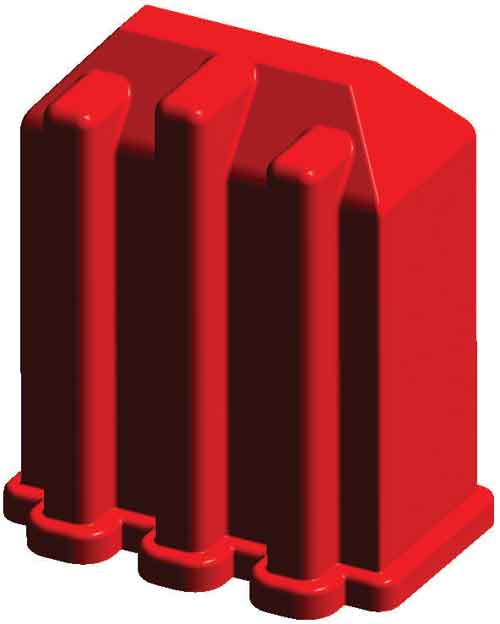
(a) Part Design – Box-like Model;

Nominal Wall – Variable Wall Thickness.
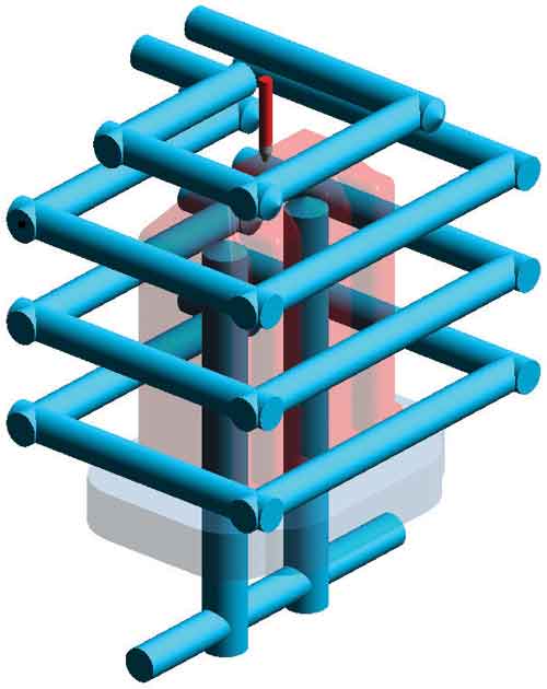
a) Cooling Design – Standard Approach
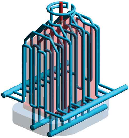
Cooling Design – Conformal Approach
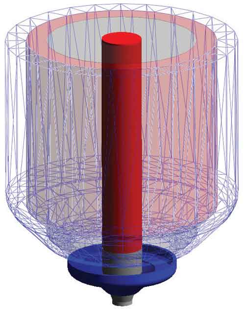
Simulation Model – Hot Drop Body.


All original equipment manufacturers (OEMs) design product with specific performance characteristics and aesthetic qualities in order to generate sales—be it a new product or a revision of an existing one. One of the earliest phases of product development is prototyping, during which samples are created. These sample products are used to determine consumer/user acceptance and to test for actual product performance. During this testing and marketing stage, it is learned which product features work well and are well received by the consumer, including look and feel. Often target price is also established during this stage. Once consumer-approved, the product geometry with accompanying features becomes non-negotiable for the remaining steps leading to full production. Whether it is a flawlessly shiny surface resulting in a mirror-like gloss, a second-shot of TPE adding a soft-touch grip or a ribbed wall section adding stability and strength, the OEM paying the bill is unlikely to concede to design changes to the very features that tested well and gave the program the green light towards full production.
The fact that poor design of some of these product features may increase the cost of manufacture does not necessarily mean that the OEM is willing to pay significantly more or change them to help ensure achieving the target market price. It is not unusual at this point for the OEM to tell the molders quoting the project, “You figure it out. You’re the experts.” The molders then go out for tooling quotes and let the tool shops know that they want pricing on a full range of cavitation to achieve piece part cost targets. The molder will also want cycle time guarantees—that is, the molder will want low cycle time guarantees. Herein lies the challenge placed into the moldmaker’s hands: meet target molded part pricing even if some part features are outside good design principles for manufacturing.
Simulation Study
Of all the factors that directly impact piece part cost—part design, resin selection, press size, operator functions, tooling design, tight tolerance values, etc.—which can we affect and control as moldmakers? In essence, moldmakers seek to know which choices can be made at the very beginning of tool development that have significant potential to achieve (or even lower) production cost targets. Cycle cooling time is an obvious choice and the tool’s cooling design directly affects cycle cooling time. The purpose of this simulation study is to help quantify the affects of tool cooling design choices on cycle cooling time. This hopefully will help our tooling group to make wise design cost versus part production cost decisions at the earliest possible tool design stage.


To complete this study we used 3D simulation in an effort to validate the best practices in cooling system design for the greatest possible efficiency of cycle time across an array of molding materials, tooling materials and wall thickness while insuring maintenance of quality in the molded part. The variables selected for control and review include:
Molded Plastic Material Family – Amorphous (PC) and Semi-crystalline (PP)
Part Wall Thickness – Relative thin wall (1.5mm) to relative thick wall (3mm)
Tool Materials for Inserts – High quality tool steels (H-13 and S-7)
Cooling Design – Standard and Conformal
Processing control parameters include melt feed system design, melt temperature, fill speed, packing time, packing pressure percentage, ejection system design, ejection temperature, solidification volume, and coolant flow rates. The feed system used here is a valve gate because it is a common choice for parts produced in high-production tooling. The melt temperature for each material is the nominal value published by the material supplier. The fill speed selected for each run is determined so as to not exceed 80 percent of the maximum recommended shear rate or shear stress. Packing time is terminated based upon gate freeze estimate and the packing pressure is set to 70 percent of the required injection pressure at the switchover point of 98 percent filled. The ejection method used here is a stripper plate applying pressure around the base perimeter of the part. Ejection is actuated at the moment key elements within the part reach the published ejection temperature for each material.
Parameters that will not be considered include the effects of material additives, surface finish and draft angle (sticking), tool venting (gas trapping), secondary cooling, post-mold handling, machine-related affects, final dimensions/distortion and product performance. These (and more!) are design considerations that can affect final cycle time and subsequently should be considered during the design cycle; however, they are not included in this project for practical reasons of control and reasonable simplicity.
Molded Plastic Family
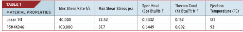
The two chosen materials for this project are (PC) LEXAN 141 and (PP) P5M4K046. Lexan 141 is an amorphous structured unfilled, engineering-grade material that is very commonly chosen for thin-walled applications because of its processability, impact strength, clarity and cost. P5M4K046 is a semi-crystalline structured unfilled, engineering-grade material that is very commonly chosen for its processability, strength, chemical resistance and relatively low cost. Both materials have good material database values for simulation use. Some of the material properties of each of these materials are listed in the Table 1.
Part Geometry
Although there is naturally a limitless array of possible part geometries, virtually all plastic molded part geometries can be placed into three general categories: plane-like, box-like or cylinder-like. And of these general categories, box-like can be argued is the most common. So then this project uses a box-like molded part for review. The design of the part is not modified except for the variable of wall thickness.
Unlike part geometry, wall thickness is limited. Limits in wall thickness are directly related to material choice and processing method. Here we have limited our process to injection molding and our material choices to PC and PP, so then our nominal wall variables are 1.5mm through to 3.0 mm thick. Both materials process well at these wall thickness values and thus it is reasonable to assume a general-purpose molding press will do the job. Of course, a greater wall thickness range is possible given the processability of both materials, but the 1-3 mm range will cover a strong representative group of typical part designs for these materials (Table 2 and Figure 1a,b).
Tooling Materials
The two chosen materials for this project are tool steel H-13 and S-7. The tool steel often referred to as H-13 is commonly used for core and cavity blocks in high-production tooling. The S-7 tool steel is a common choice for inserts that are in physical contact with or will have moving contact with core and cavity blocks. Steel grades A & D are often selected for small insert options, but they are not used in any of these simulations; their thermal performance is assumed to be insignificant relative to the H and S steels that comprise the majority of steel mass adjacent to molding surfaces. Both H and S steel types have good material database values for simulation use.
Cooling Design
Cooling design is commonly completed near the final stage of tool design. And the common cooling features are often chosen based upon what can still fit into the cavity or core blocks, what has been successfully used before or what is commercially available. Most often cooling lines are simple drilled holes that are crossed horizontally, vertically, or angled and plugged as needed to form a coolant path around the vacant tool cavity into which molten plastic will be presented for curing during the cycle. This type of circuit is references as a standard cooling design (see Figure 2a).
Only when cooling is deemed far more important than say ejection, does cooling design deviate from the ‘standard’ approach. Here we will differentiate cooling as being like the standard approach relative to a cooling design that is more near specific to the unique part design, which is referred to as ‘conformal’ (see Figure 2b). Conformal cooling is best achieved through direct metal laser sintering (DMLS), if the application fits within the DMLS limitations. Other ways of engineering cooling into the tool do exist, but are not covered in the scope of this project.
The cooling media is water, turbulent flow is assured through design, and the temperature of the coolant is as given by the material specification sheet.
Modeling Details
Gating Approach
The melt feed system design (see Figure 3) is identical in every case except for the valve gate diameter. In each model, the valve gate diameter is sized to match nominal wall. Melt channels above to the gate are progressively sized upwards starting at the gate diameter. Fill speed is determined based upon 80 percent of the maximum shear stress or shear rate, whichever is achieved first.
Processing Variables
Each material has specific processing parameters, the recommended values are typically provided by the material supplier. For each of our two chosen materials these recommended values are used and are not altered during simulation. Fill times are determined based upon the achieving 80 percent of the published maximum recommended shear values. Note that because this evaluation includes four different nominal wall thickness values—the models for each of which requires an appropriately-sized valve gate diameter—fill speeds will be unique to each model and each material.
Results
Effective Cooling Time
The cycle cooling time results of the models when using Crystalline Polypropylene and when using Amorphous Polycarbonate are shown in the Tables 3a,b. Each case of measured cooling time % change (reduction) is based upon the standard value that results from the use of H-13 steel and the standard cooling design. This is compared against the conformal cooling design.
These results indicate a significant potential for savings in cycle cooling time if the use of a standard cooling design in the tool does not meet the (originally established) cycle time expectation. This is true of both crystalline and amorphous materials; however, the magnitude of savings varies between materials. Notice also that the magnitude of potential savings varies with wall thickness.
The trends these Tables indicate are important. Understanding the trend will help us anticipate what can be expected in applications that use similar, yet different materials from those used here as well as the relative wall thickness.
For example, how much cooling time variation (% reduction) can be anticipated if an alternative grade of crystalline material (say Nylon PA) was selected as the molding material or if an alternative grade of amorphous material (say Polystyrene PS) was selected? The values noted in these Tables are probably good values, but only for reference purposes.
Another example could involve determining the relative cooling time increase (or decrease) if the nominal wall of the part has to be increased (or decreased) from one design to another. Again, the Tables can be used as reference values while considering the economical and engineering impact of original design choices and changes.
Summary Brief
Reduced Cycle Time = Reduced Part Cost
Part cost is reduced, profit margin is realized, and the customer relationship is enhanced through faster production cycles and/or lower scrap rates, if conformal-like cooling design is deemed necessary while reviewing tool design.
The degree of cycle reduction is clearly related to the choice of cooling design. Here in these Tables we see that the greatest cooling time reduction (43%) is for a crystalline material of wall thickness near 2 mm, but the savings falls off both as the wall thins and as the wall thickens. Engineering judgment is needed to determine if the savings from designing conformal-like cooling into the tool is worth the added cost and added leadtime of the tool.
The results in these Tables may have matched what an experienced plastics engineer would have already anticipated, but the magnitude of the (cycle) changes often cannot be determined without the aid of 3D simulation.
How much ($$$) can be saved depends upon annual production levels and the product lifetime. Armed with at least a general knowledge of the % cycle time that can be saved through use of conformal cooling along with reliable production expectations, a tooling engineer can easily determine if the additional tool cost investment is worthwhile.
Improved Part Quality
Quality is improved due to better heat balance through the core and cavity surfaces. The temperature range through all tool surfaces is narrower in those cases in conformal cooling design. Therefore the part cools more uniformly while it freezes, and subsequently it will have less localized stress that can act as the agent for distortion. The time required to achieve tool approval can be shortened if a lack of distortion makes possible realization of the ever-increasing dimensional and quality standards prevalent in today’s new product designs.
Reduced Tool Cost/Increased Tooling Sales
Although use of more conformal-like cooling design usually increases cost, the tool production cost may actually be less if the ‘total cost’ calculated up to final tool approval is used as the accounting benchmark. Increased sales can also be noted as a benefit if the success of projects implementing this tooling strategy sets a new standard of creativity or uniqueness, thereby setting this forward-thinking moldmaker apart from other tooling sources.
Implement Best Practices
In today’s global competitive market, every choice made during the product development process must be a careful consideration of materials and processes in order to help ensure the customer’s success and thus ultimately the success of the tool and molding vendor. Every cost-saving opportunity should be evaluated by an experienced development team and implemented if the numbers make a strong case for the opportunity. Going beyond the normal tool building practices to achieve a unique outcome is sound business strategy, but only if the scope of the project and the customer relationship merit the investment. The customer must recognize, support and value the resources being deployed by the moldmaker.
The best practices discerned through this project clearly include applying purposeful cooling design when the product design and production needs can be best met through non-standard tooling approaches.
Selecting alternative tool materials and applying new cooling techniques can help reduce cost, improve quality, and achieve a new level of design success for the business willing to accept the challenge of carefully pre-engineering tooling for challenging new part designs.


Related Content

Advances in P20 Steel Potentially Eliminates Need for Stress Relieving After Rough Cutting
Omega Tool Corp. compares conventional, new P20 grades side by side in production fascia tools, finds no downside.
Read More
Quickly Troubleshoot New Molding Defect with Moldfilling Software
SyBridge Technologies analyst compares original, new Moldflow process simulation results, solves molding defect without tool needing to be taken out of production.
Read More
Hybrid Milling/Drilling Machine Reduces Total Mold Machining Time
MSI Mold Builders now squares, plus drills and taps eye-bolt holes on 50% of its tools in a single setup using a five-axis milling/drilling center with a universal spindle.
Read More
OEE Monitoring System Addresses Root Cause of Machine Downtime
Unique sensor and patent-pending algorithm of the Amper machine analytics system measures current draw to quickly and inexpensively inform manufacturers which machines are down and why.
Read MoreRead Next

Conformal Cooling: A Tool in the Toolbox to Build a Better Mold
Moldmakers are just starting to scratch the surface of what can be done with conformal cooling, which involves an additive approach.
Read More
How to Use Continuing Education to Remain Competitive in Moldmaking
Continued training helps moldmakers make tooling decisions and properly use the latest cutting tool to efficiently machine high-quality molds.
Read More
Are You a Moldmaker Considering 3D Printing? Consider the 3D Printing Workshop at NPE2024
Presentations will cover 3D printing for mold tooling, material innovation, product development, bridge production and full-scale, high-volume additive manufacturing.
Read More