
Controlling the Melt Delivery System Heat Source
Understanding the heating systems along the melt delivery path is critical to setting up a robust process and properly diagnosing problems.
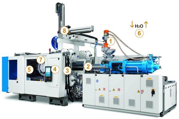
This article reviews key strategies for controlling the melt delivery system (4). Image courtesy of KraussMaffei.
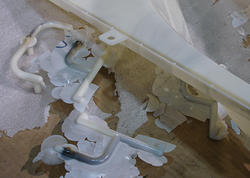
In this example, use of a cable adaptor made from incompatible materials resulted in degraded material. Image courtesy of Rich Oles.


In injection molding, energy management—thermal energy, not electricity—requires understanding how energy is applied and removed as a plastic pellet travels through the screw and hot runner system (in this case, the heated melt delivery system). Without this fundamental knowledge, a mold can be set up for failure during a molder’s first sample run. To avoid this outcome, the molder first needs to understand the body being heated and its contact to the world around it (heat sinks), and then the basic components of a conventional heating system: the energy source (heaters), body temperature sensors (thermocouples), power and control systems, hot runner controller, and cables and adapters.
The energy source is a heater that can be soldered, clamped or pressed into position. It heats the vessel (the barrel or hot runner manifold system) containing the plastic. Problems can result from wiring, heat-sink and moisture issues. Heaters can be wired in series or in parallel, but parallel is the more common method.


A heat sink is an engineered contact point used to minimize the energy loss in a hot runner system. It occurs where the heated hot runner makes contact with the mold. Once a heat sink is present, the system cannot heat up properly, which causes the power to cycle on and off more frequently than planned. As a result, the system struggles to reach the set-point temperature, which can impact performance and cause part defects.
A heat sink can also prevent a thermocouple (TC), a temperature-measuring device, from receiving the signal that a nozzle or manifold has reached the set-point temperature for the system. This can cause an overrun and ultimately degrade the resin in the melt delivery system. Another TC issue is cross wiring the TC and heater in the barrel. This could lead to a TC for one heater controlling another heater, resulting in unplanned temperature overruns and underruns.
TCs require proper location and wiring. When a particular TC type is connected to a cable or an adaptor made from a dissimilar material, the temperature may be read in the wrong location. This can be extremely difficult to identify if the operator has no prior experience with these devices.
When moisture is present inside the heater and full power is applied, the moisture reaches the boiling point (expanding at a rate greater than the heater sheath can withstand). This can result in a break in the heating element, commonly known as heater failure or burnout.
To determine the appropriate operating temperature for the injection molding system, the molder uses a watt-to-mass calculation based on the cubic units of the body being heated, heater layout (including surface area contacting the body), heater wattage, TC placement, planned heat sinks and the maximum time it takes to get the body to a specific temperature. If not calculated properly at the beginning of a project, the body being heated will never reach the correct operating temperature.
Power and control systems use the TC signal to control the power output and cycle. This is critical to keeping the resin at the planned temperatures throughout the melt delivery system. Modern molding machines use a human machine interface (HMI) to set, monitor and troubleshoot temperature-related issues. There also are a number of hot runner controllers available that are independent of the press. This may be an attractive option, as a separate controller can be upgraded more frequently while remaining more cost-effective, and can be moved from press to press. Today, more molders expect the moldmaker to test and document the hot runner manifold system’s performance prior to mold shipment.
A modern hot runner controller with capabilities to accurately and quickly diagnose root cause is a true efficiency gain for the molder or moldmaker who is attempting to diagnose TC, heater, cable or adaptor issues. For example, test results can give the moldmaker an opportunity to correct a manifold issue prior to delivery, preventing a wasted sample. Common issues like pinched wires and heat-sink problems can also be identified with the hot runner controller, and resolved quickly.
Cables and adaptors connect the power source to the heater and the TC to the control system. Cables should be safe, with no cuts or pinched wires, and connection pins should not be bent or pushed back, and should be correctly seated in the plug. If adaptors are necessary, compatible wire materials should be used.
Power sources also are an important consideration. All transformers must be wired and grounded correctly, and cables should be rated for the appropriate amp load. The types of power and TC plugs should also be considered. One common connector plug type, the PIC 12, includes power (or TC) pins that snap into place. This can be a source of problems over time or with improper use, as these pin connectors can push out of the connector, yielding an open TC or heater circuit that can cause a lost or inconsistent connection, and poor system performance.
Issues with heated melt delivery systems are often misunderstood and misdiagnosed. The basic information provided here is designed to help resolve the majority of heat-related issues experienced during the molding process.


Related Content

How to Implement a Remote Validation Process
A review of the setup and use of a remote mold validation kit.
Read More
Molds, Hot Runner Systems, Digital Technologies Highlight Sustainable Production
The Molding Solutions network at K Show displays Männer, Foboha, Synventive, Thermoplay, Priamus, Gammaflux and other external partners and their new or proven technologies for molding and moldmaking.
Read More
Mold Builder Uses Counter-Intuitive Approach for Mold Challenges
Matrix Tool Inc. answers customers’ hard questions with creative solutions for cavity spacing, tool sizing, runner layout and melt delivery that reveal the benefits of running in a smaller press size at lower cavitation but higher yield.
Read More
Power Sliding Clamps Enable Faster Mold Changes
Distributed in North America by Globeius Inc., the MouldPro Power Sliding Clamps can accommodate a range of different mold backplate sizes and thicknesses.
Read MoreRead Next

Plastic Injection Molding Starts with the Pellet
This is the first article in a new series that will examine the injection molding process by breaking down the path a plastic pellet takes as it is transformed from Pellet 2 Part. It covers what every moldmaker should know about raw materials, including the fundamentals of viscosity curves, Melt Flow Index, Melt Flow Rate, shear and more.
Read More
The Pellet Enters the Melt Delivery System
Choosing a hot or cold runner system is a decision for the molder and moldmaker that must balance the processing window with budget and time.
Read More
Initial Pellet Contact is the Screw
Here’s what every moldmaker should know about an injection molding machine’s reciprocating screw, which is often misunderstood and applied to the process incorrectly.
Read More