
Closing the Automation Loop
By using self-correcting manufacturing, moldmakers can maintain their competitive edge and continue to reduce the labor component in their products.
Share
Read Next


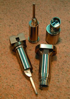
Sampling of hard metal parts machined unattended in the cell.
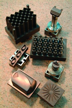
Sample of electrodes and hard metal parts machined automatically in the cell.
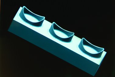
Solid model of electrode part acts as the master virtual gage in the cell.
Many mold shops have organized their plants according to a cellular concept in which families of parts are completely produced in a grouping of different types of machines and inspection stations. The level of automation varies from shop to shop. Some use robots for loading and unloading and others use human hands. Some use automatic inspection equipment while others use manual dial indicators. However, most progressive shop owners agree that the goal is to continue to further automate processes to keep companies alive in an industry that is in peril. U.S. moldmakers are competing against foreign companies that have substantially lower labor costs. Assuming that all other costs are equal, the only way a shop can stay in business is to continue to reduce the labor component in its products; it can maintain its edge by the creative application of technology.


The Ultimate Automation Scenario
The ultimate automation scenario is unattended manufacturing, including startup, qualification and process control-whether the lights are on or off. This requires the integration of a dynamic automatic inspection and analysis system that delivers both live qualification and process control feedback to the machining cell. With these systems, the process makes the necessary in-process corrections to tooling and work offsets to maintain part tolerance based on real-time process data. Gauge manufacturers call this methodology closed-loop automatic feedback gauging. Engineers have coined the term self-correcting manufacturing (SCM). This ability to automate the error correction feedback-to communicate-has been the missing link and the barrier to full unattended machining for many moldmakers. The result is the ability to manufacture completely different geometric shapes as if they were a family of parts, in small batches, with both increased accuracy and decreased cost.
Anatomy of an Automatic SCM Cell
The premise of SCM is that all parts must be manufactured using the same procedures within specific operations. In CNC milling for example, they are loaded into the machine tool, machined, removed, inspected, analyzed, flagged for process adjustments and pass or fail based on tolerance. As such, there are six primary components to fully automatic SCM: part transport, workholding, machining, inspection, integration and analysis.
Fundamental Cell Structure, Considerations and Sequence
A universal workholding/palletizing system enables any component to be either loaded or unloaded with robotics, regardless of its geometry. Thoughtful process planning based on workflow requirements is essential when using pallets to avoid excessive refixturing and risking positional accuracy in one of the subsequent operations. As an example, when a company's current system uses more than 7,000 macro pallets as the workholding system for all of its equipment-CNC machining centers, lathes, wire and sinker EDMs, grinders and measuring machines-served by a robot, the workpiece is mounted to the pallet after heat treating, and is not removed until all finishing operations have been completed. This greatly reduces the fixture errors induced in multiple setup scenarios.
Other technology requirements in an electrode and hard-steel manufacturing cell include a highly accurate, thermally stable CNC machining center equipped with both high-speed machining (HSM) and high-speed communication capabilities. The next requirement in a cell is in-process inspection on a coordinate measuring machine (CMM). Measurement, analysis and feedback occur in quick succession in the SCM process. The CMM sends the measure point data the CAD system where nominal dimensions of the part model are compared with this data, and error analysis is performed. Again, the correction data is fed back to the machine tool if an offset correction is required, and the part is validated to a volumetric tolerance. Finally, the part is unloaded to a designated space on the pallet tower. When starting a new run:
- The first part of the new run is loaded into the machine tool.
- The part is machined.
- The part is unloaded from the CNC, then loaded and measured on the CMM.
- The measurement data are sorted via customized software to correlate the tool number and surface cut.
- Size and position errors are separated with best fit algorithms using the CAD model.
- The corrections are translated into the machine tool's coordinate system and sent.
- The points are compared to maximum and minimum material condition solid models to qualify the part has met all designated tolerances.
- Parts that have excess material are flagged for recutting, which are remachined at the end of the run, and remeasured.
- Concurrent to this analysis, the second part is loaded and the loop begins.
Communication Integration
Once the manufacturing equipment is in place, it all boils down to communication through software. The first step is to determine what is the process' natural variation. Contributors to natural variation include machine accuracy, fixture repeatability, thermal stability, tooling quality and measurement certainty. Each of these factors is critical if the goal, for example, is to make parts volumetrically accurate within +/- 3 microns. Inaccuracies compound across the entire cell. For successful unattended manufacturing, the machine must impart the least amount of variation into the process. A tall order, since the machining environment, by its nature, introduces the most variables. Tools heat up. There are issues with coolant temperature and pressure, tool wear, rpm and torque changes on the cutter. Tools break. Chip management is another issue. The potential problem list goes on, particularly surrounding tooling, the spindle and software. There is no question that a volumetrically-accurate, temperature-compensating machining center, with an excellent spindle and an integration-friendly control system, is of paramount importance. This is the area where prove-out time is well spent before shutting the lights out, going home and getting a good night's rest while your cell remains active (see Machine Tool sidebar at end of article).
Custom Software Development
Once the system's natural variation is calculated, the next step is to establish good mathematical formulas for managing that variation and for separating size and position error. Operators manually perform this task, so a program must be written emulating this logic within any metrology software program. For instance, an operator may choose not to make a correction on a 0.0001-inch error because this could be within the natural variation of the process. However, three such errors in a row is a trend and should be corrected. This logic needs to be captured in the control process. Size and position errors must be simultaneously separated and solved. A hole, for example, must have its measure data best fit for positional error and then with this translation applied, solved for size error.
The next step is to establish a CMM measuring technique that will deliver the same measurement data that your operators currently produce. For example, if the part is measured on a fixture, these same fixture datums must be used in the CMM's measurement program to generate results that correlate. Many companies find discrepancies in measurement data based on datum selection alone.
Then, solid models need to be created of the perfect part—at the mean of the desired manufacturing tolerance. These models serve as the master virtual gages in the system to which the machine parts are compared.
At this point, custom software needs to be written to manage the sequence of passing data from CMM to CAD to the CNC system. This is where it's essential to ensure that the machine tool's CNC can speak to the rest of the group. Once the sequence and communication integration is programmed, custom analysis algorithms need to be developed that will resolve errors based on each piece of equipment's reference frame. For instance, an EDM machine may be corrected in work offset, C-axis rotation, burn depth, orbit, etc. The software must sort the workpiece error and solve it based on the machines and process modifiable variables. Finally, generate software to function as a dynamic work queue to manage the workflow on the workholding pallet tower.
Beyond Unattended ... What's Next?
Only about 1 percent of all parts fail in the SCM cell. The cell is programmed to keep operating. If one batch of parts can't be machined within tolerance after a few tries, it moves on to the next job in the queue to remain productive. If, by chance, that job isn't running properly, evidenced after a few parts, the entire cell will halt to avoid an exorbitant scrap expense. If the system stops during it, wouldn't it be helpful to know there is a problem or if the cell has completed all the jobs and is finished? The next phase on the unattended machining horizon is communication to the outside world. In that scenario, a camera is placed in the cell and if it stops running for any reason, a preprogrammed cell phone number is signaled. The receiving person then goes to a PC, logs into the web cam, and actually directs the cell to take whatever step is necessary at the time.
The End Is Worth the Means
The result of SCM is the ability to manufacture completely different geometric shapes as if they were a family of parts, in small batches, with increased accuracy and decreased cost-completely unattended. It does take time and investment to establish a totally automated cell; yet, with thoughtful planning and good communication among management, employees and the pieces of equipment, the results are extraordinary. The payoff is measured not only in profits and productivity at individual companies, but more importantly for loftier goal-the very survival of an industry in peril.
| The Machine Tool-Heart of the Cell |
| Good communication is at the crux of every successful endeavor, whether it's an interpersonal relationship or one piece of equipment speaking to another. In a manufacturing cell, good communication is important. In one that operates unattended, with lights on or off, it's essential to success. The piece of equipment with the most potential problem in communicating, along with a host of other variables, is the machine tool. If the computer system acts as the brain of the cell, then the machine tool is the heart.
"We tried four different machines in its cell and none were satisfactory with communication, accuracy and dependability," says Bill Kushmaul, president and owner of Tech Mold, Inc.-a moldmaker based in Tempe, AZ. "The ideal machine had to be different, had to offer the ultimate in accuracy and the correct communication protocol and durability. We ran a series of tests on several machines under consideration so we would base our decision on facts, not feel." The areas scrutinized were spindle thermal control, volumetric accuracy, acceleration/deceleration rates and the ability of the controller to process and relay data. These aspects were reviewed after each machine produced a spherical part designed by Tech Mold. "For what we are trying to achieve with our cell, we had to go for the champion. We had to go for the machine with excellent volumetric and machining accuracies and that could repeat from part one to part three hundred. That capability also speaks of superb stability-dynamically and thermally. We also had to make sure that the manufacturer and its distributor would bring the support system that we would require undertaking such an ambitious project." With all the machine criteria considered, the decision was made to purchase a Mitsui Seiki VL30 with advanced linear motor technology and a Fanuc control system featuring the latest suite of control and communication software. |


Related Content

The Benefits of Hand Scraping
Accuracy and flatness are two benefits of hand scraping that help improve machine loop stiffness, workpiece surface finish and component geometry.
Read More
How to Eliminate Chatter
Here are techniques commonly used to combat chatter and guidelines to establish a foundation for optimizing the moldmaking process.
Read More
Plastic Prototypes Using Silicone Rubber Molds
How-to, step-by-step instructions that take you from making the master pattern to making the mold and casting the plastic parts.
Read More
Hands-on Workshop Teaches Mold Maintenance Process
Intensive workshop teaches the process of mold maintenance to help put an end to the firefighting culture of many toolrooms.
Read MoreRead Next

Advances in Automation for Mold and Die - High-Performance Machining and EDM
Recent developments in automation are providing benefits for the high-performance machining (HPM) of electrodes and steel mold components.
Read More
How to Use Strategic Planning Tools, Data to Manage the Human Side of Business
Q&A with Marion Wells, MMT EAB member and founder of Human Asset Management.
Read More
Are You a Moldmaker Considering 3D Printing? Consider the 3D Printing Workshop at NPE2024
Presentations will cover 3D printing for mold tooling, material innovation, product development, bridge production and full-scale, high-volume additive manufacturing.
Read More