
Chasing the Perfect Feed Rate
Get more than just reduced machining time with NC program feed rate optimization software.
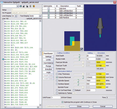
Adjust, test and fine-tune the NC program optimization settings repeatedly without re-running the simulation.
Cycle time can be reduced significantly by automatically optimizing feed rates for the amount of material being removed.


Most moldmakers will agree that reducing NC machining time is one of the best ways to improve efficiency and increase profitability. Understanding the need for feed rate optimization is relatively simple, but it can be difficult to achieve without good information about the current cutting conditions. CAM systems have no concrete way to determine the volume or the amount of material removed by each cut. Therefore, programmers are forced into the difficult task of visualizing the material removed in order to get in-process information.
Determining optimum feed rates traditionally has presented NC programmers and machinists with a number of problems. Typically, the selected feed rate represents a compromise between tool life, cycle time and the worst-case cutting condition encountered. This rate may end up being the ideal feed rate for the part where the most material is being removed or where the worst cutting conditions are encountered. Unfortunately, it may also waste time and even create poor cutting conditions elsewhere.


Feed rates can be adjusted by hand during the machining process. Experienced machinists listen for the telltale signs of excess cutter load and then manually alter the feed rates at the machine accordingly. The only override adjustments the machine tool operator typically makes is to slow down the feed rates as needed. And most CNC controls have very limited capabilities for speeding up feed rates when conditions permit.
With advances in cutting tools, tool materials and CAM software, it is increasingly critical to use the right feed rate for each and every cut. However, many CAM systems use machining strategies and cut patterns that are not efficient for common operations such as open boundaries, roughing cuts on complex shapes, complex pocketing or planar roughing.
Some software packages can detect and machine excess material, unmachined areas and surface blend areas, but for this useful automation, efficiency is usually sacrificed. Therefore, a lot of time is wasted cutting air and feeding slowly across the part’s surface. Additionally, the tool path may plunge the cutter into material at an incorrect or inefficient angle. Poor feed rates contribute to excessive cycle times, bad workpiece finishes, increased cutter wear and broken tools.
Powerful, Intuitive Productivity Tool
Software that enables programmers to automatically optimize NC toolpath programs is essential. This software can read the NC program file (G-code program or direct CAM system output) and automatically divide the tool motion into a number of smaller segments (determined by user-defined settings in the software). The software will then assign the best feed rate based on the amount of material removed in each segment.
Finally, this software outputs a new NC program identical to the original one but with improved feed rate settings. It will not alter the tool path trajectory. Even tool paths that use continuous tangent cutting motion rather than sharp, interrupted movements often benefit from feed rate optimization.
On one hand, NC program feed rate optimization software is automatic and determines the best feed rates before the NC program is even loaded on the machine. On the other hand, it uses the expertise of the NC programmer and machinist to determine the best feed rates for specific cutting conditions. Users input ideal feed rates for a number of pre-determined machining conditions. Factors such as machine tool capacity (horsepower, spindle type, rapid traverse speed, coolant, etc.), fixture and clamp rigidity, and cutting tool type (material, number of teeth, length, etc.) all affect the cutting process.
Updates that Fine Tune
In addition to these factors, other settings such as maximum volume removal rate, entry feed rate, cut depth, cut width, cut angle, cutter wear, etc., are also used to determine the optimum feed rate for each segment of cut. Software updates may include a method to adjust, test and fine-tune the optimization settings repeatedly without re-running the simulation. All the cut information is stored after running the simulation once. The moldmaker then can interactively navigate, evaluate and change the optimization settings individually on a cut-by-cut level, and the results are displayed immediately.
Typically, different types of optimization techniques are best-suited for certain stages of the machining process. During planar roughing, material is removed at a constant depth, but the width of cut varies greatly. To achieve the best feed rate for the cutting conditions, optimization software should take into account the depth of cut and the percent of the cutter width buried in the material.
Using the information provided during the verification process, the software is then able to determine the amount of material removed in each segment of the tool path. It then assigns the best feed rate using the information supplied by the NC programmer and/or machine tool operator.
During the semi-finish stage, cutting is typically characterized by widely varying cutter loads as the tool profiles through the roughing cuts to near-net shape. In order to achieve a smooth semi-finish cut, feed rates are optimized to maintain a constant volume removal rate. Optimization software will take into account the amount of material that is in contact with the cutter and the angle of the contour cuts. Along with a maximum volume removal rate specified by the user, the contact area and angle are used to determine the appropriate feed rate for each segment of the cut. Therefore, the feed rates continually change over the course of the cut in order to maintain a constant volume removal rate and produce a high-quality semi-finish surface.
Summary
Light cuts at extremely high feed rates and spindle speeds are common in today’s high-speed machining centers. Under such conditions, the manner in which each cutter tooth contacts the material is critical. Too low a feed rate produces chatter, vibration and work hardening, leading to poor surface finishes and premature cutter failure. Too high a feed rate causes excessive cutter loads and unsafe conditions that can lead to catastrophic failure of the tool, spindle, fixture and machine. Feed rate optimization solves the problem by ensuring that all cutting operations maintain a constant chip thickness. This technique works especially well in high-speed finishing operations.
Manufacturing software has made tasks achievable, which were practically impossible or extremely difficult and time-consuming a decade ago. These software innovations change the way NC machining is performed while saving time, money and resources, and each year, advancements in the technology make optimization software an increasingly powerful and intuitive productivity tool.


Related Content

It Starts With the Part: A Plastic Part Checklist Ensures Good Mold Design
All successful mold build projects start with examining the part to be molded to ensure it is moldable and will meet the customers' production objectives.
Read More
How to Manage Wall Thickness Changes in Your Mold Design
To ensure even filling and cooling, consider wall section transitions, corners and fillets, ribs and bosses, lip and rim designs and CAE flow simulation software.
Read More
Mold Innovations Power Unique Auto Lighting Elements on Hummer EVs
Diamond machining, electroforming of micro-optical inserts and modified latch-lock system help injection molds produce unique forward lighting elements.
Read More
What is Scientific Maintenance? Part 2
Part two of this three-part series explains specific data that toolrooms must collect, analyze and use to truly advance to a scientific maintenance culture where you can measure real data and drive decisions.
Read MoreRead Next

A Simple Way to Improve Communication with the Shop Floor
Generating set-up sheets, in-process inspection instructions and other documentation from simulated in-process machined features improves communication, saves time and increases accuracy.
Read More
How to Use Strategic Planning Tools, Data to Manage the Human Side of Business
Q&A with Marion Wells, MMT EAB member and founder of Human Asset Management.
Read More
Are You a Moldmaker Considering 3D Printing? Consider the 3D Printing Workshop at NPE2024
Presentations will cover 3D printing for mold tooling, material innovation, product development, bridge production and full-scale, high-volume additive manufacturing.
Read More