
Challenges of Multi-Cavity Co-Injection Molding
Simulation shows that, to be effective, these types of molds must be designed with consideration for how the materials will be distributed throughout them.
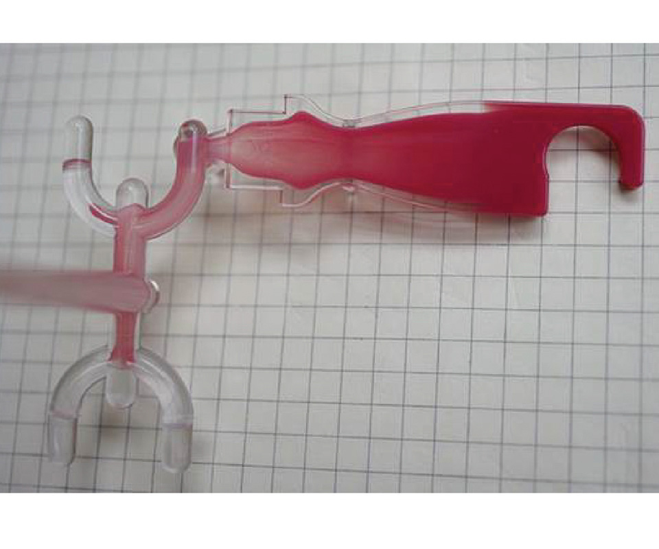
Fig. 1 - The distribution of the core and skin materials in this co-injection molded part was affected by the injection flow rate and the characteristics of those specific materials.
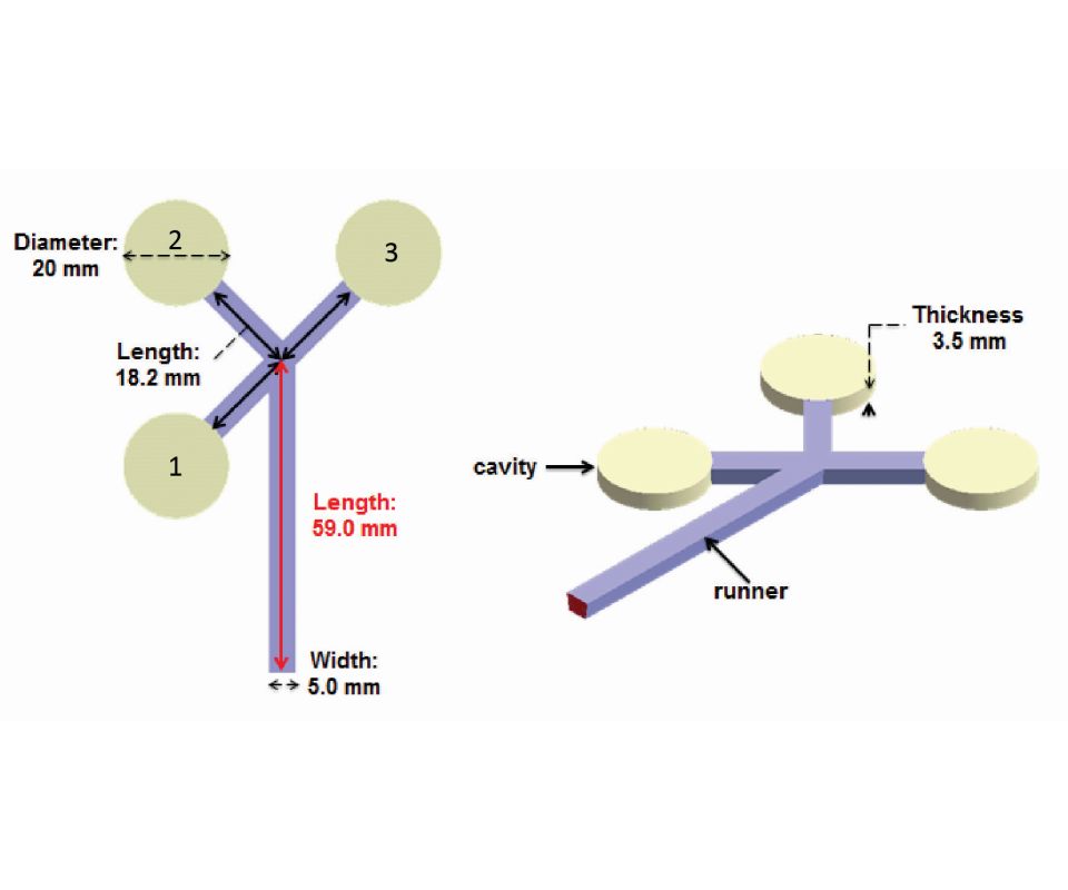
Fig. 2 - These cavity and runner geometries were used for a simulation experiment. Each of the three cavities (marked “1,” “2” and “3”) is 20 mm in diameter and 3.5 mm thick. The 5-mm wide primary runner is 59 mm long, and the three secondary runners are 18.2 mm in length.
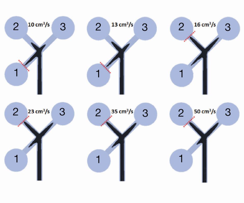
Fig. 3 - Here, the core material in the branch marked “1” reaches the cavity first when the injection flow rate is at 10 cubic centimeters per second. However, when the injection rate is increased to 16 cubic centimeters per second or higher, the core material in the branch marked “2” reaches the cavity first.
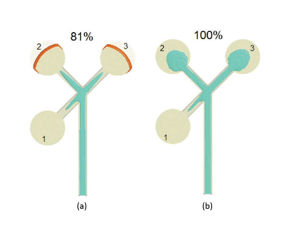
Fig. 4 - At 81-percent filling (left), Cavity 1 is already filled by the skin material, so there is no room for the core material. It must flow into Cavities 2 and 3.
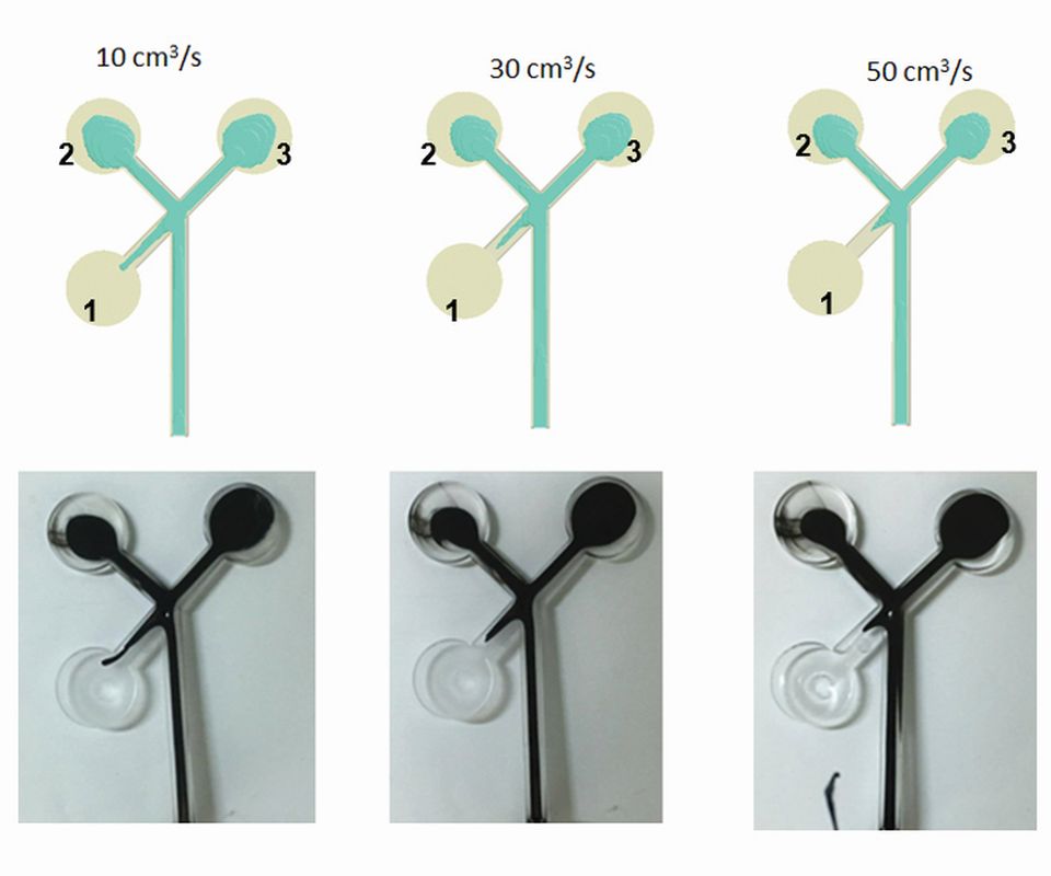
Fig. 5 - Validation results show that using high or low flow rate to manipulate core penetration behavior does not work.
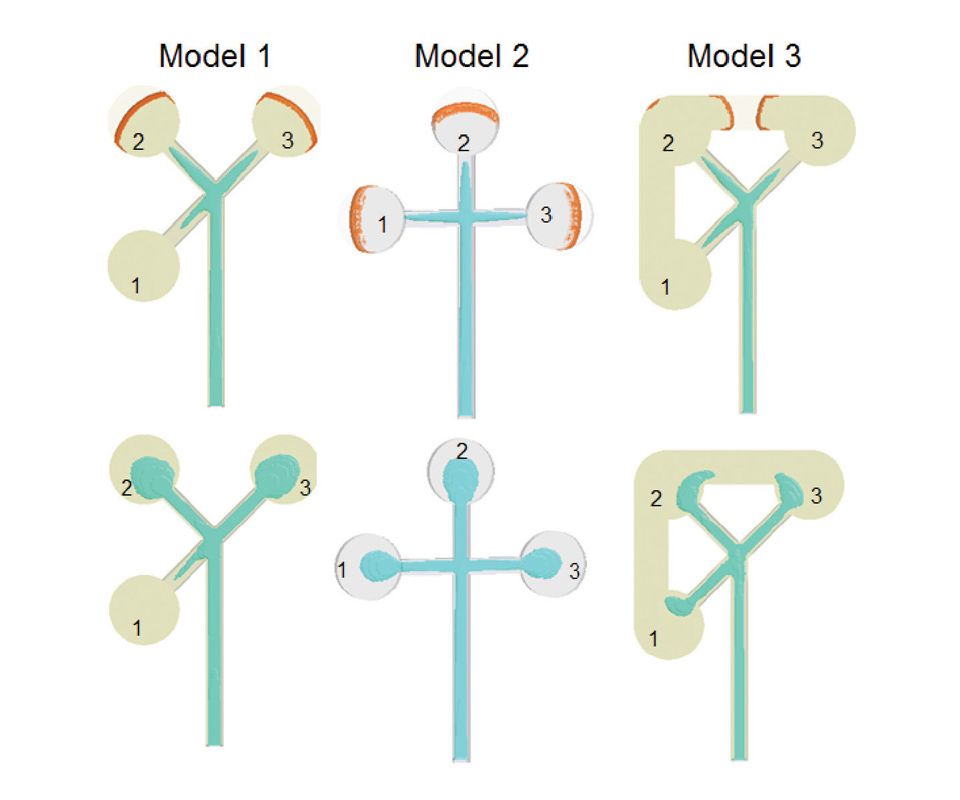
Fig. 6 - Cavity design influences the skin/core distribution in multi-cavity co-injection-molded products. Here, Model 2 shows that if the angle of the 45-degree runners in Model 1 is modified to a more symmetrical design, a more uniform skin/core distribution can be achieved. If a runner structure with a 45-degree angle cannot be revised, a connector can be added between each cavity to ensure better skin/core distribution, as shown in Model 3.


Multi-cavity co-injection molding offers a great deal of flexibility in terms of part development. The ability to combine different materials or colors, for example, makes it an attractive option for the manufacture of automotive components and structural reinforcement products. Process benefits also include reduced material waste, decreased costs and improved part quality.
Designing these types of molds presents unique challenges, however. The same general guidelines used for developing a single-cavity co-injection mold cannot be fully applied to the design of a multi-cavity co-injection mold.


Co-injection molding involves injecting two resins simultaneously through a single gate to form a multi-layer molded part composed of a “skin” and a core material. The skin material is injected into the mold cavity first and is immediately followed by injection of the core material. As the skin material flows into the cavity, that material that covers the cavity walls freezes and the rest of the material flows down a center channel. When the core material enters the cavity, it displaces the skin material in the center of the channel, pushing the skin ahead, where it continues to freeze on the walls.
The key to successful multi-cavity co-injection molding is a uniform distribution of core and skin materials throughout the molded part. This is difficult to achieve, however, and is strongly affected by material properties and process conditions. For example, the distribution of core and skin materials in the co-injection-molded part shown in Figure 1 was affected by the injection flow rate and the characteristics of those specific materials. The flow pattern of the core material should be uniform all the way back to, in this case, the “fork” runner structure.
Experimenting with Mold Geometries
To find solutions to the challenges of designing an effective multi-cavity co-injection mold, we experimented with injection flow rate and cavity design, using a computer-aided engineering (CAE) tool to simulate and analyze potential molding scenarios. Figure 2 shows the cavity and runner geometries used for this simulation experiment, which were taken from a 2003 study conducted by W.M. Yang and H. Yokoi on the flow behavior of core material in a similar part. Each of the three cavities (marked “1,” “2” and “3”) is 20 mm in diameter and 3.5 mm thick. The 5-mm-wide primary runner is 59 mm long, and the three secondary runners leading to each of the cavities are 18.2 mm in length. The material used in this study for both the skin and the core was a general-purpose polystyrene.
In co-injection molding, the skin material is injected to fill a certain percentage of the mold and then the core material is injected to finish filling the part, at an established ratio of skin material to core material. This study used a skin-to-core ratio of 72-to-28 to validate the change in core penetration behavior.
Figure 3 shows the flow-front penetration of the core material at various injection flow rates. Here, the core material in the branch marked “1” reaches the cavity first when the injection flow rate is at 10 cubic centimeters per second. However, when the injection rate is increased to 16 cubic centimeters per second or higher, the core material in the branch marked “2” reaches the cavity first. Using the low-viscosity polystyrene material and an injection flow rate of 16 cubic centimeters per second (at the skin/core ratio of 72-to-28) reveals a crucial transition flow rate when the leading core material penetration changes from Branch 1 to Branch 2. This transition can be attributed to the high shear stress in Branches 2 and 3, which results in more core material entering the second and third cavities.
However, penetration of the leading core material in the runner-filling stage does not guarantee proper skin/core distribution in the final molded product. Figure 4 shows very poor skin/core distribution. At a filled volume of 81 percent, Cavity 1 is already filled by the skin material, so there is no room remaining in that cavity for the core material. It must flow into Cavities 2 and 3. Note that using a high or low flow rate to manipulate core penetration behavior does not work. Figure 5 validates this phenomenon, showing an actual molding result.
To better manage the skin/core distribution in final molded products, it is necessary to consider the influence of cavity design. In Figure 6, for example, if the angle of the 45-degree runners in Model 1 can be modified to a more symmetrical design, a more uniform skin/core distribution can be achieved, as shown in Model 2. However, if the runner structure with a 45-degree angle cannot be revised, a connector can be added between each cavity to ensure better skin/core distribution, as shown in Model 3. This part of the experiment clearly demonstrates that cavity design does influence skin/core distribution in multi-cavity co-injection-molded products.
The dynamic behavior of core material penetration in multi-cavity co-injection molding is a complex issue. Core material penetration is sensitive to injection flow rate, material properties and process conditions. In this experiment, flow patterns and core penetration were observed in a forked runner structure during multi-cavity co-injection molding. It showed that leading core penetration with a low-viscosity material is affected by the injection flow rate. Finding the transition point at which the leading core penetration switches from one branch to another is essential for understanding core penetration behavior.
Moldex3D, EPS FloTek


Related Content

MoldMaking Technology's Most-Viewed Content 2022: Products
MMT shares the five top-viewed technologies, equipment and services of 2022 in each Engineer, Build, Maintain and Manage tenet based on Google Analytics.
Read More
What is Scientific Maintenance? Part 2
Part two of this three-part series explains specific data that toolrooms must collect, analyze and use to truly advance to a scientific maintenance culture where you can measure real data and drive decisions.
Read More
Leading Mold Manufacturers Share Best Practices for Improving Efficiency
Precise Tooling Solutions, X-Cell Tool and Mold, M&M Tool and Mold, Ameritech Die & Mold, and Cavalier Tool & Manufacturing, sit down for a fast-paced Q&A focused on strategies for improving efficiencies across their operations.
Read More
Mold Innovations Power Unique Auto Lighting Elements on Hummer EVs
Diamond machining, electroforming of micro-optical inserts and modified latch-lock system help injection molds produce unique forward lighting elements.
Read MoreRead Next

Reasons to Use Fiber Lasers for Mold Cleaning
Fiber lasers offer a simplicity, speed, control and portability, minimizing mold cleaning risks.
Read More
Are You a Moldmaker Considering 3D Printing? Consider the 3D Printing Workshop at NPE2024
Presentations will cover 3D printing for mold tooling, material innovation, product development, bridge production and full-scale, high-volume additive manufacturing.
Read More
How to Use Continuing Education to Remain Competitive in Moldmaking
Continued training helps moldmakers make tooling decisions and properly use the latest cutting tool to efficiently machine high-quality molds.
Read More