
Broadening CAM Applications for Barrel Cutters
This alternative cutting tool geometry, along with the right CAM software, can help moldmakers reduce finish-machining times.
A CAM toolpath approach that supports alternative cutter geometries, such as conical barrel cutters, can lead to significantly reduced machining times in moldmaking applications. Images courtesy of Open Mind Technologies USA.
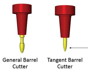
Fig. 1 - This schematic of traditional barrel cutter geometries highlights the side profile of the tangent barrel cutter. A small arc segment of a large swept radius makes the cutter’s interaction with the workpiece surface mimic that of a very large ball end mill.
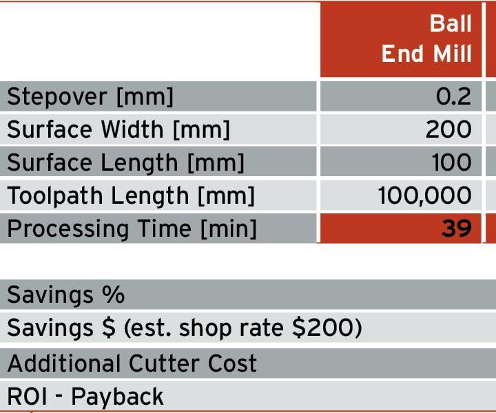
Fig. 2 - A conical barrel cutter can save machining time and offer increased tool life, reducing overall process costs.
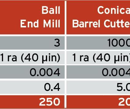
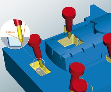
Fig. 3 - The envelope of material removed by the conical barrel cutter allows for a very large stepover distance to the next pass while still producing a fine surface finish.
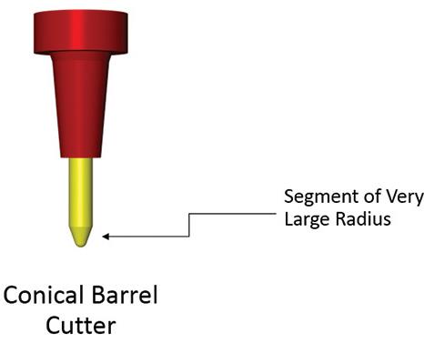
Fig. 4 - The conical barrel cutter design has an effective cutting surface that is inclined by 10 or 20 degrees for side cutting, or as much as 70 degrees for bottom cutting.


The barrel cutter has been available for more than 20 years and offers powerful machining benefits, yet its application primarily has been confined to specialty solutions (for example, the flank side of a screw machine, the blades of axial compressor blisks or as special form cutters to match the geometry of a workpiece). The main culprit has been the lack of a CAM programming concept. Only a limited number of CAM software products support these types of tools, so few shops have taken advantage of them. Another barrier to market has been the fact that barrel cutters commonly have been custom-ground to each individual order, and special-order cutters mean lengthened delivery times, limiting commercial viability.
Recent developments in CAM software have expanded the application set for barrel cutters, however, and some manufacturers are now able to quickly produce these tools, in some cases offering them as catalog items. To fully understand the importance of these developments, shops first need the basics on barrel cutters and their economics.


Cutter 101
A barrel cutter is a solid carbide end mill with a specially ground cutting edge. Its gross dimensions are similar to commonly available ball end mills and bullnose cutters, so it can be ground from existing stock by the cutting tool manufacturer. The unique feature of the barrel cutter can be seen in its side profile, which shows a small arc segment of a large swept radius (see Figure 1). This causes the cutter’s interaction with the workpiece surface to mimic that of a very large ball end mill.
A barrel cutter costs more to manufacture than a standard ball or bullnose cutter, however, so some customers might question how increasing cutter cost is a process improvement. The answer is that the barrel cutter can save machining time and offers increased tool life, which means that the cost of the overall process is reduced (see Figure 2).
The barrel cutter is more challenging for CAM software to program, however. Because the profile of the cutter is not a hemisphere like that of a ball end mill, the software has to control both the point of contact between the barrel and the workpiece within the limited arc segment, and the center point of the circle from which the barrel surface is derived. The programmed point in the machining instruction is then along the cutter centerline, which is usually the tip location. This calculation is more complex than for a ball end mill, but it is still governed by geometric mathematics. Control of the barrel cutter also has to be managed with a scheme for collision detection and avoidance.
The benefit of having a large radius on the cutting surface is that the envelope of material removed by the cutter allows for a very large stepover distance to the next pass while still obtaining a fine surface finish (see Figure 3). A tool path with large stepover distances greatly reduces overall cutting time. The smaller distance the cutter travels (due to bigger steps) also means cutter life and cost is amortized over many more parts.
The barrel cutter can also have a ball end ground on its bottom. Again, depending on the control available in the CAM software, cutter life can be increased by using the barrel side for large surfaces, while using the ball end for operations such as rest machining in corners or detailing organic features. Basically, the cutter can have two lives, further improving its economics.
A benefit of the barrel cutter that is difficult to measure, but one that cannot be ignored, is reduced machining time. In addition to the time saved on individual machines as a direct result of using the novel cutters and associated programming techniques, barrel cutters enable shops to meet their milling production demand using fewer milling machines, which leads to a reduction in capital costs, lower electrical consumption and potentially smaller floor space needs. These benefits are not as easy to calculate relative to the cost of a cutter, however.
Roughing to Finishing
A major development in CAM software over the past five to 10 years has been advanced roughing techniques that focus on cutter engagement or volume of cut. These techniques use a more complex algorithm than traditional collapsing-pocket methods that reduces the impact of severe cutting conditions for entry or corner cuts. The result has been improvements in roughing times of 40 to 75 percent, which in turn reduces machining cycle time. These roughing techniques have then exaggerated the relative times of finish cuts, however, so the critical focus then becomes reducing finish-cutting time.
For example, consider mold components that demand high precision, especially in terms of mating surfaces. Organic surfaces generally have to be finished with ball end mills, but what about mold lock surfaces, especially in larger molds where swarf cutting is not an obvious solution? Is it possible to use barrel cutters on those surfaces to gain a dramatic reduction in machining times? The answer is a resounding yes!
A traditional barrel cutter’s geometry (whether a general barrel cutter or tangent barrel cutter) limits its ability to successfully machine tall planar faces without toolholders or spindles getting in the way, or by requiring extra-long cutters. Changes in the traditional tool design, driven by developments in programming software, have resolved this problem and now enable some barrel cutters to achieve reduction in machining times on planar faces by as much as 90 percent. In moldmaking, a conical barrel cutter can be used for large planar surfaces or ruled surfaces such as those found in mold lock geometry and parting planes.
The distinction in the conical barrel cutter design is that the effective cutting surface is not exactly perpendicular to the cutter axis. Instead, the cutter is inclined by 10 or 20 degrees for side cutting, or by as much as 70 degrees for bottom cutting (see Figure 4). The cutter looks similar to a crayon tip, but with a large radius on the side instead of a line-segment profile. This simple yet dramatic addition to the barrel cutter’s geometry allows the tool, holder and spindle to tilt away from the surface being machined. This makes it possible to take advantage of extremely large stepover distances in areas never before possible.
For example, with some cutter geometries, the barrel radius can be as large as 1,000 mm and the stepover distance can then be 6 mm. The difference between the barrel cutter’s large radius and a tapered end mill is imperceptible. In this example, the deviation is 0.005 mm. Though geometrically similar, however, the conical barrel cutter behaves differently than the tapered cutter’s swarf milling with multiple steps.
There are several advantages to using conical barrel cutters:
• The cone angle moves the cutter axis, cutter holder and spindle away from the workpiece cutting surface. This allows the use of shorter cutters, which are less expensive than, and offer increased stiffness and manufacturing technology parameters over longer cutters.
• The cutter makes single-point contact, as opposed to tapered cutter segments that make profile contact and lead to deflection and double-cut situations when the cutter contact is larger than the stepover distance. Blending between successive passes of the conical barrel cutter is far superior to strip milling with the side of a cutter.
• Thermal expansion/spindle growth has limited impact on conical barrel cutters compared to the bottom surface of a face mill that could be used to machine mold lock surfaces. Deviations in cutter length have negligible impact on the barrel surface location and on the machined part.
One machining task the conical barrel cutter cannot always accomplish is cutting completely to the corner or adjacent part surface. In these cases, the ball end on the barrel cutter must then be used to reduce the amount of remaining material and for rest machining. This can lead to five-axis simultaneous solutions or in some cases 3+2 indexed milling. Thus, a total solution is possible with perfect blending.
To be practical for moldmakers, CAM software calculations using conical barrel cutters must be made efficiently. Because available programs feature strong mathematics and need to compute fewer tool paths, those calculations can be made quickly. To produce good tool paths, the calculation process must consider remaining material; collision detection; point spacing; smooth approaches; and feed rate control for transition, approach and cut moves. With these items under consideration, the programming can be as simple as selecting a target surface, and defining the cutter dimension and stepover distances.
In the end, the multi-disciplinary innovation of CAM toolpath strategies using new cutter geometries can have a huge impact on machining times in moldmaking applications.
OPEN MIND Technologies USA Inc.


Related Content

How to Eliminate Chatter
Here are techniques commonly used to combat chatter and guidelines to establish a foundation for optimizing the moldmaking process.
Read More
Laser Welding Versus Micro Welding
The latest battle in finely detailed restoration/repair of mold materials.
Read More
Revisiting Some Hot Runner Fundamentals
What exactly does a hot runner do? If you’ve been in the injection molding industry for any length of time, you might think the answer is obvious, but it is not.
Read More
Plastic Prototypes Using Silicone Rubber Molds
How-to, step-by-step instructions that take you from making the master pattern to making the mold and casting the plastic parts.
Read MoreRead Next

CAM Automation is a Process, not a Goal
Automated NC programming requires a strategy to yield improved productivity, quality and consistency.
Read More
Are You a Moldmaker Considering 3D Printing? Consider the 3D Printing Workshop at NPE2024
Presentations will cover 3D printing for mold tooling, material innovation, product development, bridge production and full-scale, high-volume additive manufacturing.
Read More
How to Use Continuing Education to Remain Competitive in Moldmaking
Continued training helps moldmakers make tooling decisions and properly use the latest cutting tool to efficiently machine high-quality molds.
Read More