
Balancing Act
Consider elements of the entire tooling assembly, including the tool, holder and holder components, to optimize productivity.
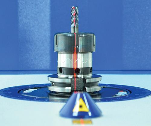
To increase speed without sacrificing tool life or finish, the entire tool assembly should be balanced to the U.S. machine tool industry standard of G2.5 at a spindle speed equal to the fastest spindle in the shop. Images courtesy of Haimer USA.
Balancing the entire tool assembly and using a holder system with repeatable runout accuracy will enable faster cutting without sacrificing tool life.
To improve productivity, a shop must accurately determine just how fast a given tool can run. This requires a look at the balance, rigidity and runout accuracy of the entire tooling assembly, including the tool, holder and holder components.
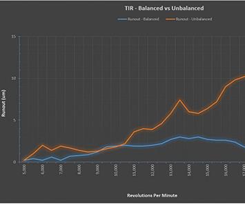
Imbalance in the tooling assembly can create runout at high speeds, even though there is no measurable static total indicated runout (TIR).


A conversation about optimizing machining speeds often begins and ends with talk of the cutting tool, but it should include consideration of the entire tooling assembly. Many times, the expert bringing in the cutting tool technology is not the same expert bringing in the holder interface technology. The result is two compartmentalized components. Instead, to improve productivity, the entire tooling assembly, including the tool, holder and holder components, should be part of the conversation. This requires a look at the key elements of balance, rigidity and runout accuracy to truly determine how fast a given tool can run. Eliminate or reduce one of these elements, and the net result is a reduction in cutting speeds to compensate.
Most shops don’t realize they are sacrificing productivity to compensate for other missing elements, however. They assume they have hit the limit of their cutting tool and are unable to push it any faster. The truth is, they just need to optimize other aspects of the assembly in order to cut faster. Let’s take a look at how the elements of an entire tooling assembly work together to optimize speeds and feeds, and allow for lights-out machining to increase cutting productivity.


Optimum Performance
According to Merriam-Webster, the word optimum means “the amount or degree of something that is best or most effective.” In terms of machining speeds and feeds, optimum parameters are only achieved when the surrounding elements directly influencing the tool are also at optimum. This means balance, rigidity and concentricity.
Balance is perhaps the most misunderstood element of the entire tooling assembly. Most people understand that balance is the even weight distribution from one side of the holder to the other, but they don’t understand how balance variables impact measurement, when balance should be measured and how much imbalance truly impacts machining results. Many believe that a holder that is balanced “out of the box” is good enough, however, whether or not this is true depends heavily on the type of holder. If the holder has moving mechanical parts, it’s likely that balance out of the box is not good enough.
Balance is important not just in the use of high-speed spindles during high-speed machining to process molds and complex parts from hardened steel. At higher speeds, it might be more critical, like the need for a seat belt when you are driving fast in a car. But does the seat belt become unimportant when you are driving around town at slower speeds? Of course not, and the same holds true for a balanced tool assembly. Whether it is a 2-mm ball mill running 20,000 rpm in hardened steel, an indexable face mill running at 8,000 rpm or a boring bar running at only a few hundred rpm, balance accuracy impacts finish, tool life, spindle wear and speed.
To increase tool speed without sacrificing tool life or finish, the entire tool assembly should be balanced to the U.S. machine tool industry standard of G2.5, at a spindle speed equal to the fastest spindle in the shop. (G numbers are vibration threshold limits measured in millimeters per second.) The reduction in vibration with proper balance translates to less chatter and improved finishes. And combined with improved dynamic runout accuracy, it also reduces uneven cutting edge load on cutting tools, which increases their life span. Most shops are able to realize average increases in speed of 15 to 20 percent while still seeing tool life and finish improvements.
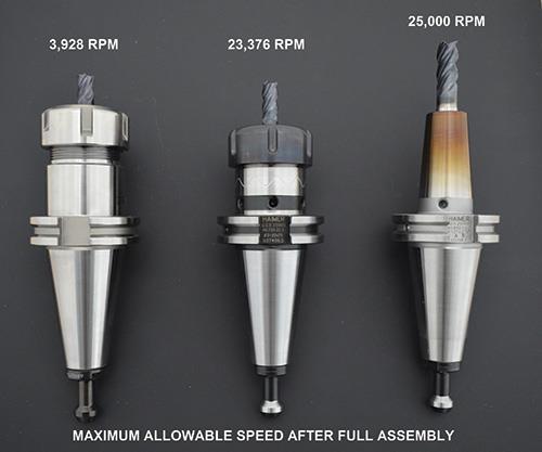
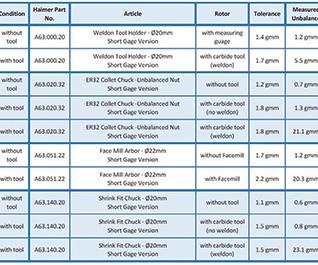
Toolholder components, such as collets, collet nuts, side-lock screws and retention knobs, all have a profound impact on the balance of the overall assembly. This is a foreign concept to many shops and only becomes clear when they measure it for themselves. For example, a simple pull stud can take a holder that is balanced to G2.5 at 25,000 rpm and reduce it to G2.5 at less than 4,500 rpm. Collet nuts and Weldon flat end mills can have the same or greater impact, because most collet nuts are not balanced by themselves, and Weldon flat tools are imbalanced by their very nature (a hunk of metal is missing from one side).
Many shops today are still not getting the balance they think they are. They pull a new collet chuck out of the box and assemble it with the collet, cutting tool, collet nut and pull stud. It lays there shiny and new next to its “Certificate of Balance,” which only certifies that the holder is balanced naked, meaning without a tool, collet, collet nut and/or retention knob. So, what they thought was balanced to G2.5 at 30,000 rpm is actually only balanced to run about 5,000 rpm.
To guarantee that the entire tooling assembly is properly balanced, the best option is to purchase a balancer or use a balancing service. There are many options for quality balancing machines, which can range in price from $35,000 to $65,000 on average, depending on the desired features and functions. Most shops realize a return on this investment in less than a year. For example, one major automotive manufacturer reduced unplanned tool changes from 57 percent to 7 percent by simply balancing all assemblies before machining. Balance is as fundamentally important to improving cutting productivity as inspection is to ensuring part tolerances or CAM software is to ensuring efficient tool paths.
Rigidity is another essential tool assembly element, because the more rigid the tooling, the faster one can machine. Rigid is defined as “not able to be bent or moved easily.” This explains why shorter tool overhangs, shorter holder gage lengths and thicker wall thicknesses in chucks promote greater rigidity. So another way to approach improving rigidity is to inhibit movement.
For example, consider the spindle taper interface. This is one critical area of the tool assembly that offers little opportunity for lessening movement, because it is limited by the taper tolerance of the machine socket and holder taper. Basically, you cannot control the taper of the holder, so you cannot fix its inaccuracy. The only option is to use higher quality holders. The accuracy of this taper cannot be overstated, and there are simply no shortcuts in manufacturing to achieve the tightest tolerances. And like balance, equipment to measure tapers by trained operators with time to interpret complex ISO taper tolerances are not often readily available in most shops.
A test conducted at a major research university’s metrology lab, using high-precision measuring instruments and standards, found only two of 15 toolholders from different manufacturers actually met or exceeded the AT3 standard. “AT” is an ANSI/ASME and ISO standard that ranges from AT1 to AT11. The lower the number, the tighter the tolerance. To avoid compromising on speed to make up for poor taper interface, shops should invest in holders with true AT3 or better taper tolerances.
Concentricity is the relative accuracy with which a rotating tool aligns with the center line of the spindle. Deviation from spindle center line is commonly called runout. This runout is a core function of accuracy, but it also plays a key role in tool wear. While in the cut, a cutting tool with runout is naturally taking larger bites with one side of the tool than with the other. This uneven cutting load leads to faster tool wear and shorter tool life. The first thing most operators do when the cutting tool is wearing too quickly is to slow everything down to gain back more acceptable cutting tool performance.
To cut faster without sacrificing tool life, improve the runout accuracy of the entire tool assembly by balancing the entire tooling assembly and by using holder systems with repeatable runout accuracy. Repeatable systems are those that do not have components that wear easily, such as collets or sleeves, and can impact runout accuracy after only a few months.
To move towards lights-out machining, use a system (cutting tool, holder and holder components) that not only has runout repeatability, but one that boasts total indicated runout (TIR) of 3 microns or better. Unmanned machining is all about absolute tool life predictability, from one tool change, and one shift change, to the next.
The ideal solution for this type of repeatability in accuracy and balance is shrink-fit tooling, because it includes no moving mechanical parts that can wear and impact performance. The added gripping torque and rigidity of this type of tooling is also unmatched, because shrink-fit holders engage the tool shank completely over 360 degrees on multiple planes. The collapsibility of the bore, in combination with this gripping zone, makes the gripping torque of high-quality shrink holders quite powerful. Pair this with the absence of gripping torque deviation, which is often present in other systems that require specific torque specifications or tightening instructions, and you have a system that will reduce errors and streamline machining processes. Beware that not all shrink-fit holders are created equal, however. Like anything, you usually get what you pay for.
Once speeds and feeds have been optimized and the tooling is maxed out, have another conversation about the entire tooling assembly. Check the holder taper to see if there is any rust, which would indicate poor taper tolerance. Measure to see if runout is still 0.0002 inch or better, then measure and balance the entire assembly, and check the runout accuracy again to see the difference in tool wear, part finish and spindle load. When it all shows improvement, you can bank the cost and time savings.


Related Content

Laser Welding Versus Micro Welding
The latest battle in finely detailed restoration/repair of mold materials.
Read More
Considerations for Mold Base Material Selection
Choosing the right material can greatly affect the profitability and cost of your application.
Read More
Plastic Prototypes Using Silicone Rubber Molds
How-to, step-by-step instructions that take you from making the master pattern to making the mold and casting the plastic parts.
Read More
Moldmakers Deserve a Total Production Solution
Stability, spindle speed and software are essential consideration for your moldmaking machine tool.
Read MoreRead Next

A New Standard for Roughing in Moldmaking
A look at how to use modern toolholding technology with assurance that the cutting tool will not pull-out and how to increase feeds and speeds during heavy roughing.
Read More
How to Use Strategic Planning Tools, Data to Manage the Human Side of Business
Q&A with Marion Wells, MMT EAB member and founder of Human Asset Management.
Read More
Reasons to Use Fiber Lasers for Mold Cleaning
Fiber lasers offer a simplicity, speed, control and portability, minimizing mold cleaning risks.
Read More