
Afraid of Pushing Your Cutting Tools?
How advanced software and cutting tool technologies take the fear out of pushing your tools.
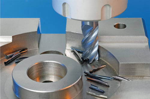
A chatter free tool in action.
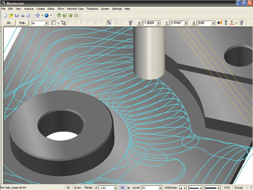
Screenshot showing high efficiency machining (HEM) toolpath.

Dynamic milling constantly adjusts the toolpath to ensure the most efficient cut possible and allows use of the entire tool flute length, often eliminating the need for multiple depth cuts.


To put it simply, CAD/CAM software developers create code that controls tool motion. The operating parameters we live by are that the toolpaths be efficient, safe and respectful. In other words, the software creates tool motion that is economical and smart, yet won’t cause harm to the tools, machine or operator. And while that’s a commendable approach, akin to the Hippocratic Oath— “first do no harm”— there are new software and cutting tool developments that allow programmers to crank up the speeds, feeds, depths-of-cuts and the resulting productivity gains.
Many software developers are working toward this end, but one has a family of helpful features—dynamic milling and plunge turn for lathe work, as well as included empirical operating data from cutting tool manufacturers, so users get all the benefits these cutting tools are designed to deliver.1
How Does a Tool Want to Cut?
The features and intelligence that software developers and cutting tool manufacturers have in the box right now are all well and good, but here’s the catch: they must be used! It may be uncomfortable—even downright scary—to reach beyond the safe zone of programming for any tool condition. That is, programming using the old 50-percent radial stepover formula.


For example, a 1 inch tool should go down into the material ½ inch. It’s the classic, safe approach. The machining motion of choice is normally climb milling, but this can be inefficient in terms of moving the tool out of and into the next cut (retracts and entry motion). A zigzag machining approach can minimize wasted tool motion, but is inefficient for the cutting tool since the cutting motion switches between climb and conventional milling.
When the job is done, tooling buyers might wonder why their new, expensive cutters that promised getting in and out of the mold faster didn’t work out as they had hoped. Doing something the same old way provides the same old results.
Pushing cutting tools to get the benefits they promise has a lot to do with understanding how the tools should be applied. For one thing, most cutting tools abhor zigzag machining due to changes that take place when switching from climb to conventional milling. The more aggressive you want to be; the more important it is to maintain a consistent approach.
Also, these cutting tools can thrive, maintaining aggressive metal removal rates when used with a smaller radial sidestep, but it typically requires advanced programming knowledge, toolpaths, calculations and experimentation for this approach to benefit over older techniques. This is an area that has been addressed by building the aforementioned toolpaths and cutting tool knowledge into the CAM software.
For example, in one CAM software, when a programmer selects a certain high efficiency machining tool, the interface changes and won’t allow the programmer to choose a sidestep greater than 10 percent. In fact he or she can only choose 10, 7 or 5 percent. Now, because a smaller sidestep is selected, the interface guides the programmer to make up for it by increasing the depth-of-cut. A depth-of-cut up to a maximum of three times the diameter of the tool is recommended.
So instead of ½- inch deep, this half-inch tool would be optimized by going 1 or 1-1/2 inches deep. Further, because the radial sidesteps are so small, the software suggests increasing the feedrate and spindle rpm too, so that the chip thickness is correct and the tool is shearing the material, which is the way it’s designed.
Heat—the enemy of carbide—is managed appropriately in this scenario with most of the heat being transferred into the chip. Other benefits include higher material removal rate on machine tools equipped with high-speed spindles, less spindle horsepower required and longer tool life—all of which lower production costs. Suddenly, those expensive tools aren’t expensive at all! They are delivering the promise, and the net result is less cost per mold.
Go For It!
Most who run these tools, even at the lowest high efficiency machining setting, will be venturing into a zone of aggressiveness they have never experienced before in machining applications, particularly roughing operations. It takes courage, but let the new software intelligence be your guide. If tools are used appropriately, the way they are designed to be applied, the result will be real productivity gains for your shop.
In light of all this being said about throwing caution to the wind, you know the capability of your particular machines better than anyone else. If you choose high efficiency machining and 12,000 rpm, and the program says that the machine needs to run at 500 inches a minute to create the right chip load, you have to ask yourself if that is possible with that particular machine and workpiece. If it can only run at 180 inches a minute, then very thin chips will result and burn up the tool. The sensible thing to do is lower the high efficiency machining factor.
Intelligent tools don’t relieve the responsibility of the user to be a smart machinist. The good news is that even at the lowest settings, the dynamic software approach and advanced tooling will result in safe and significantly improved roughing throughputs.
References
1 Currently, selected 2D Dynamic and 3D OptiRough toolpaths now support Iscar high efficiency machining (HEM) solid carbide tools and calculations as well as radial chip thinning factor (RCTF) speed and feed calculation functionality.


Related Content

Products and Services for Multiple Moldmaking Needs
New year, new technology roundup! Featured here is a collection of product offerings, from profile milling cutters to industry-specific CAD/CAM software to innovative hot work tool steels.
Read More
How to Manage Wall Thickness Changes in Your Mold Design
To ensure even filling and cooling, consider wall section transitions, corners and fillets, ribs and bosses, lip and rim designs and CAE flow simulation software.
Read More
Tolerancing in Mold Design, Part 2: Using GD&T to Address Conventional Tolerancing Issues
Mold designers can achieve a single interpretation of workpiece functionality when following the American Society of Mechanical Engineers Geometric Dimensioning and Tolerancing standard.
Read More
What is Scientific Maintenance? Part 2
Part two of this three-part series explains specific data that toolrooms must collect, analyze and use to truly advance to a scientific maintenance culture where you can measure real data and drive decisions.
Read MoreRead Next

The Many Dimensions of Feature-Based Machining
Simple does not mean minimal. FBM is a powerful tool that can save many different types of users’ time and money. Here’s why.
Read More
How to Use Strategic Planning Tools, Data to Manage the Human Side of Business
Q&A with Marion Wells, MMT EAB member and founder of Human Asset Management.
Read More
Are You a Moldmaker Considering 3D Printing? Consider the 3D Printing Workshop at NPE2024
Presentations will cover 3D printing for mold tooling, material innovation, product development, bridge production and full-scale, high-volume additive manufacturing.
Read More