Share
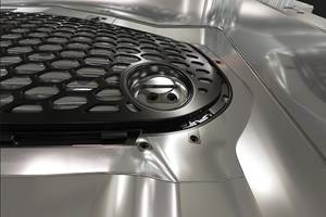
The necessity for productivity reigns throughout manufacturing, and that certainly includes moldmaking. Recent CAD/CAM software advancements can help achieve significant improvements throughout the shop and moldmaking process from quoting, programming and roughing operations through to finishing, deburring and shop connectivity.
New tools in CAD/CAM packages are geared toward CAD solid model preparation and are designed to make the file cleaner, smaller (data size) and easier to work with. In toolpath creation, dynamic roughing tool paths continue to become smarter, and now even finishing operations are enjoying a boost with new algorithms. Also, certain CAM packages offer highly focused moldmaking tools for electrode creation, core/cavity model separation and parting line creation.
Important aspects of all this software advancement for mold shops include gaining the necessary CAM power to take advantage of the latest in cutting tool designs, probing, process simulation and verification, and data gathering and monitoring.
CAD for CAM
The first step to streamlining the moldmaking process is model preparation. It begins with the CAD solid model file. Most CNC tool paths are generated by directly editing the solid model versus sketching or wireframe-based modeling. It’s vitally important for the CNC machine programmer to work with a model in its cleanest form. This will create the most optimal and efficient toolpath strategies to cut the mold cores, cavities and various inserted components.
When a designer or operator inputs or views a CAD model file in the CAM system, they may see defects, especially if the file was transferred from person to person and CAD system to CAD system, which is common practice. New utilities in the CAM program can query the solid model, discover defects, and even fix the model, such as filling in gaps and deleting unnecessary data remnants.
The next step is model editing, and there is new software functionality for viewing, reducing and simplifying the solid model for the programming task at hand. Take, for example, a mold with a large drafted face that also has small detail features. When programming the roughing strategies, the programmer only needs to consider the large face because the small details will be machined later in the process. New CAM tools allow the programmer to delete those smaller, more complex features on the model and focus on cutting the larger drafted faces, which simplifies the programming and reduces the required time it takes to complete this task.
The first step to streamlining the moldmaking process is model preparation.
When it comes to the design side of CNC programming, hole making — almost every mold has holes, ports, and threads — has experienced several advancements, including smart consolidation of hole making functionality. For example, certain CAD/CAM packages combine the operations that each hole requires, such as center drilling, drilling, reaming and tapping.
The emphasis now is more on the feature, the hole as a systematic process, and what needs to be done from start to finish, rather than selecting and programming each operation in the program. One such new feature allows the solid creation of four or five conventional solid model operations in one dialogue. Previously, a counterbored hole with a small counter sink on top would require the use of several independent features in the software. While that is still a valid approach, it can now be done in one selection via one associative solid feature. That associativity has the added benefit of being capable of modification later in the process. For example, making the counter sink a couple of millimeters larger. The programmer can quickly and easily click on that hole system as a feature and change it without having to remodel the entire feature.
Cutting tool manufacturers continue to develop new profiles, so it’s important that CAD/CAM software advances accommodate futuristic combinations of these current profiles and whatever new cutting tools the future holds.
Additionally, a software advance beneficial to many moldmakers is editing surfaces. A programmer can simply click on any surface and add, remove or modify the U and V lines of that surface definition. A simple click-and-drag can completely change how that surface looks or is defined. This can be used by an advanced programmer to modify tool path behavior.
For example, the programmer can build a custom bulge in the surface to smoothly transition the tool over a fixture bolt. Or, perhaps hand polishing is required for a certain critical area and the programmer needs to leave a bit more stock on that feature to accommodate the handwork or machined blends. Changing that surface in the model is now much easier than old methods to accomplish a similar or better result.
Another advancement allows a programmer to see the solid model in a cross-sectional view, which is helpful not only at the toolpath creation stage but also when quoting a job. The estimator can readily access all the features that might otherwise be hidden, helping to understand the scope of the part, such as which machine will cut the part, required cutting tools needed, and process requirements.
Tool Paths
Once the model is in good shape, it’s time for the programmer to create the CNC tool paths to machine the mold. Newer dynamic tool paths allow a moldmaker to remove a lot of material as quickly as possible. At their essence, these tool paths constantly change the amount of engagement of the tool in the cut to ensure it is continually removing material, using the optimal chip load for the cutting condition. This can significantly reduce the time it takes to complete near-net mold roughing.
Some CAM packages today include accelerated finishing tool paths developed in conjunction with the most advanced cutting tool manufacturers. These toolpath strategies are aimed at the new oval, barrel, taper and lens-shaped forms. When programmed correctly, these cutters can allow a small diameter tool to have a large effective cutting radius at the contact point, reducing cycle time and improving surface finish.
Cutting tool manufacturers continue to develop new profiles, so it’s important that CAD/CAM software advances accommodate futuristic combinations of these current profiles and whatever new cutting tools the future holds. For example, new deburr tool paths that can reduce this secondary operation and allow mold builders to run lights out, increasing quality and throughput while reducing handwork and improving the company’s profitability.
Mold builders should ensure that their CAD/CAM system offers verification functionality to avoid crashes and the expense of scrapped parts.
Verification
A vital step once the program is created is program verification. The step involves simulating the process and the actual machine tool’s motion in a visual way before making the first cut. Simulation color codes the part, machine, stock and fixture so that, at a glance, the programmer and machinist can easily see all important details of the metal removal process, even the brand name of the machine tool on the sliding door. Mold builders should ensure that their CAD/CAM system offers this functionality to avoid crashes and the expense of scrapped parts.
Workpiece probing within the CAM software is another development that allows for complete control of the machine’s work and tool probe within the CAM programming and simulation environment. This is a necessity for lights out manufacturing because it promotes in-process control by using the probe to measure features and then update the machining process and tool data in real time, based on the results. This feature gives the machine the capability to make programmed decisions about the quality of the part without an operator.
Connectivity
Many mold shops today are at least observing, if not embracing, the emerging shift in manufacturing towards the Industry 4.0 concept of digital connectivity, data gathering and monitoring. The shop’s CAD/CAM program is essentially a platform for the shop to accomplish a variety of tasks, whether it’s metrology, robotics or digital tool management. So, it’s important for mold builders to work with CAD/CAM providers that have partnerships with machine tool builders, cutting tool developers, metrology instrument companies, and other software utilities in the industry. These partnerships help to ensure that all the pieces of the moldmaking process connect, which is the intention of Industry 4.0.
Primary trends in CAD/CAM software have remained fairly consistent and focused on the moldmaker’s primary need for productivity in recent years. This productivity extends through the entire process and shop, which drives CAD/CAM advancements that yield workpieces faster on the machine and faster off the machine with the highest quality.
About the Author
Jesse Trinque
Jesse Trinque is an applications engineer for CNC Software Inc.
For More Information
Related Content
How to Use Automation to Minimize Mistakes and Speed Mold Build Process
A guide to capturing and reusing company knowledge and experience with software automation.
Read MoreMMT Chats: Applying Bench Lessons to the Business of Moldmaking
For this MMT Chat, my guest is Mark Gauvain, one of MMT’s newer Editorial Advisory Board members who has plenty to share as he recently made the move from working for some big manufacturers to working for himself as a consultant to moldmakers and molders on procurement and technology investment strategies.
Read MoreWhat is Scientific Maintenance? Part 2
Part two of this three-part series explains specific data that toolrooms must collect, analyze and use to truly advance to a scientific maintenance culture where you can measure real data and drive decisions.
Read MoreVIDEO: Perspective on A.I. and Mold Design
Bill Genc of TopSolid shares his perspective on the benefits of and barriers to using artificial intelligence in mold design.
Read MoreRead Next
How to Use Continuing Education to Remain Competitive in Moldmaking
Continued training helps moldmakers make tooling decisions and properly use the latest cutting tool to efficiently machine high-quality molds.
Read MoreAre You a Moldmaker Considering 3D Printing? Consider the 3D Printing Workshop at NPE2024
Presentations will cover 3D printing for mold tooling, material innovation, product development, bridge production and full-scale, high-volume additive manufacturing.
Read MoreHow to Use Strategic Planning Tools, Data to Manage the Human Side of Business
Q&A with Marion Wells, MMT EAB member and founder of Human Asset Management.
Read More_970x90 4.png;maxWidth=970;quality=90)


.jpg;maxWidth=300;quality=90)
_300x250 3.png;maxWidth=300;quality=90)


