
A Practical Approach for Optimizing Your Machine, Part Two
A look at more unused optimization features in your CNC that are waiting to be unleashed with a little investment.
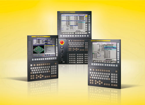
CNC product line.
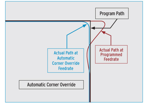
Figure 1. Automatic corner override.
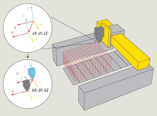
Figure 2. 3-D error compensation applied directly in the work space.
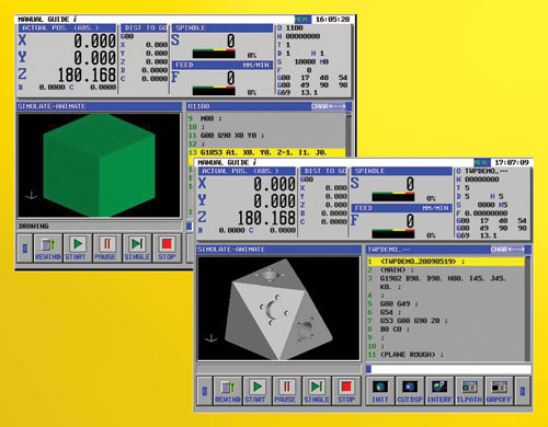
Figure 3. MANUAL GUIDE i conversational programming.
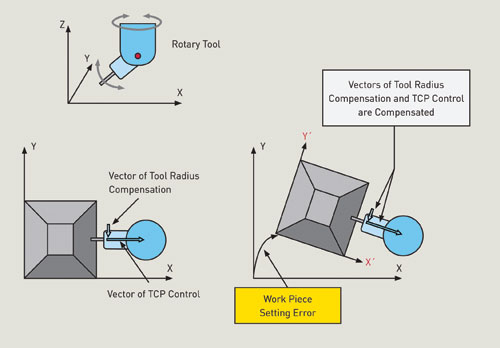
Figure 4. Workpiece setting error compensation.


In last month’s Part 1 of “A Practical Approach for Optimizing Your Machine,” we covered low-cost improvements that can be done to any CNC system with minimal investment in time and money. Part 2 will cover additional advanced optimization techniques and features, which may be more specialized based on the machine application and CNC capabilities.
Optimization Via the Addition of Advanced Performance Features
CNC manufacturers in recent years have developed many features, which can be utilized or added to enhance the operation of the machine tool. These features include:
Advanced Acceleration Control: Acceleration is the time it takes any motion system to transition from one speed to another. Limiting factors to the maximum acceleration rate in a machine tool system come from mechanical design, load inertia and servo torque. Advanced acceleration control provides features that, within the capabilities of the mechanical system, control the shape of the acceleration curve. This is achieved through pre-calculating the acceleration curve, fine acceleration control, optimized acceleration based on contour moves and acceleration jerk control.
In any programmed contour move, no matter how well the servo system is tuned, error is induced along the acceleration curve. These advanced features work to mitigate that error by including the acceleration curve in the move calculation, and shaping the resulting acceleration profile to best fit the contour profile. In addition to increasing the precision of the move, advanced acceleration control is also directly responsible for providing smoother and faster transitions between speed changes. This will result in smoother surface finishes and shorter cycle times.
Advanced Shape Control: Speed and acceleration directly impact the size and shape of the finished product. While servo tuning and advanced acceleration control can significantly reduce program path error, there comes a point where physics takes over and no amount of servo control can produce the contour required at the program speeds requested. Corners will overshoot and gouge, and contours features will simply disappear.
Modern CNCs have features to significantly reduce the effects or physics on a part without requiring the part programmer to significantly change the program to compensate for these errors. Advanced shape control features include:
Automatic Corner Override: This sets a speed transition value in the CNC which could result in an over shoot of the axes. The CNC looks ahead and recognizes the change in axes speed and decelerates the axes in the corner to reduce the overshoot (see Figure 1). It should be noted that since this feature adjusts the feedrate and acceleration rate in the corners, it could also affect cycle time adversely.
Advanced Contour Control: This feature comes in many variations, but most variations consist of any combination of the following four features:
1.) Advanced Feed Forward Control: This feature preprocesses the program path and corrects the servo following error by augmenting the path to correct for this error.
2.) Advanced Acceleration Control: By including the acceleration and deceleration curves as part of the command rather than the result of the servo algorithm, the program path can be followed more closely at higher speeds.
3.) Look Ahead Control: Preprocesses program blocks to speed program execution and aid in path correction.
4.) High Speed Processing: The addition of a High Speed processor to also speed part program execution to allow for much smaller program moves at higher speeds also aiding in path accuracy.
Many CNC’s can be easily upgraded to include these features. If these features are already present in your CNC, improvements can be realized by either attending training in order to learn the proper use of these features or by having a CNC service professional tune them to meet your particular application needs.
Optimizing Machine Accuracy
CNC systems have many features that help to achieve more precise positional accuracy. Mechanical systems have inherent inaccuracies. As the mechanical systems are compounded, the inaccuracies can be compounded. CNCs are equipped with compensations to correct for some of these inaccuracies.
Backlash and Backlash Acceleration Compensation: Used to compensate for lost motion occurring when the axis is reversed. Many times this error manifests itself as marks in the surface finish of a contoured part.
Pitch Error Compensation: This compensation is used to correct for minute mechanical errors in the pitch along the length of axis travel induced by the ball screw, rack and pinion, gear train or linear scale.
Straightness Compensation: This compensates for the geometrical inaccuracies (squareness) of the axes of the machine tool by adjusting the position of adjacent axes based on the position of the measured axis.
Temperature Growth Compensation: Machine positions along a tool vector are directly affected by the temperature of the machine structure. Machine structures can grow and shrink by finite amounts related to the temperature of the structure. Temperature growth compensation uses precise growth tables to predict and compensate for structural changes based off the inputs of temperature sensors placed in strategic locations around the machine.
3-D Error (Volumetric) Compensation: All the compensation previously mentioned contributes to machine accuracy, but (particularly on complex large machines) additional compensation applied in the work area applied directly at the tool tip is required to provide complete accuracy. 3-D error compensation provides that addition compensation (Figure 2). 3-D error compensation can be applied in 3-axis and 5-axis machines.
Compensation Maintenance: Compensations are usually set at the factory or during installation of a new machine tool. As machines wear through use, compensation requirements change, so compensations should be checked and adjusted periodically. Compensations should always be readjusted after any machine event (e.g., crash, machine relocation or mechanical service).
It needs to be noted here that these compensations are meant to improve machine accuracy not compensate for a poor mechanical system, nor can compensation work effectively on machines where the inaccuracies are not repeatable. It must be restated that if you have non repeatable errors, your machine has serious mechanical problems, which need to be addressed before any compensation can be applied.
Optimize the Machining Process Using the CNC Control
CNC’s today provide many features that can aid the user in improving the manufacturing process. This is done with the CNC’s built-in features or the CNC’s ability to interface with external devices or software designed to improve the machining process. Built-in features may include:
On Screen Conversational Programming: Very useful in situations where the operator is responsible for the CNC programming, and parts are customized and done in small batches—such as in a toolroom operation (see Figure 3).
Adaptive Control: Used to control material removal by regulating the feedrate, in real time, during roughing cycles to maintain a constant cutting load. Maintaining a constant load results in reduced cycle time, extended tool life and automatic compensation for material variation.
Advanced Tool Management: Used to automatically track tool usage and select tools with enough useful life to complete the cut, track tool positions within the machine and associate data such as offsets, programs, date codes, etc. with a particular tool.
Advanced Part Program Management: Utilizing the ability to track program usage, verify version data, organize programs in folders with extended descriptors and provide high-speed communication options to rapidly upload and download.
Workpiece Setting Error Compensation: Allows the user to adjust the coordinate system to accommodate a part that is not located ideally on the work surface without adjusting the part program (see Figure 4).
External devices that can be easily interfaced to the modern CNC may include:
Tool and Part Probes: Probe systems can be added to your CNC and machine, which can save valuable setup time and help maintain part quality. Tool and part programs help eliminate manual operations—such as tool measurement, tool offset updates, part location, work offset updates, in process gauging and first part inspections. By limiting manual intervention the margin for error drops significantly.
RFID or Barcode Tracking: Some external devices allow the operation of RFID and barcode reading in order to provide the CNC with important tool and part information. For example, tools can be embedded with RFID chips to allow the operator to scan the tools as they are loaded into the tool chain, allow the CNC to update the tool offset table for that tool’s preset data, and allow the CNC to verify the proper tools loaded in the machine for a particular job.
Optimization can be achieved in any CNC equipped machine tool. The amount of optimization required is up to you. Any optimization—whether it is minor or major—will yield improvements to your machine and process.
References
Availability of these features are limited please check with your Machine Tool Builder or CNC Manufacturer to find out if your CNC control is capable of supporting any of these features.
2 Advanced acceleration control requires implementation by trained professionals.


Related Content

Leading Mold Manufacturers Share Best Practices for Improving Efficiency
Precise Tooling Solutions, X-Cell Tool and Mold, M&M Tool and Mold, Ameritech Die & Mold, and Cavalier Tool & Manufacturing, sit down for a fast-paced Q&A focused on strategies for improving efficiencies across their operations.
Read More

Moldmakers Deserve a Total Production Solution
Stability, spindle speed and software are essential consideration for your moldmaking machine tool.
Read More
The Trifecta of Competitive Toolmaking
Process, technology and people form the foundations of the business philosophy in place at Eifel Mold & Engineering.
Read MoreRead Next

A Practical Approach for Optimizing Your Machine, Part One
An in-depth look at optimization features embedded in your CNC waiting to be unleashed.
Read More
How to Use Continuing Education to Remain Competitive in Moldmaking
Continued training helps moldmakers make tooling decisions and properly use the latest cutting tool to efficiently machine high-quality molds.
Read More
Are You a Moldmaker Considering 3D Printing? Consider the 3D Printing Workshop at NPE2024
Presentations will cover 3D printing for mold tooling, material innovation, product development, bridge production and full-scale, high-volume additive manufacturing.
Read More