
3-D, Non-Contact Scanning for Inspection: Info for Moldmakers
Understanding the differences and similarities between CMM and 3-D scanning allows moldmakers to adapt to, apply and leverage 3-D scanning technology within their shop environment.


Figure 2a and Figure 2b. These systems provide scan data of both external and internal features.
Figure 1. 3-D scanners create dense point clouds comprised of millions of measurements. Figures courtesy of CGI.
Figure 3a. Since there is no correlation between time and the number of inspection points, feature-laden parts can be inspected quickly.
Figures 4A and 4B. A point cloud is overlaid onto 3-D CAD data for calculation of point deviations. The result is a color map that yields a visual reference to part quality.
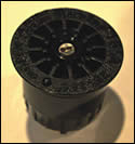
Figure 4c. Using Cross-Sectional Scanning, Hunter Industries inspected the sprinkler nozzle to determine the cause of performance issues.
Figure 3b and Figure 3c. Tightly packed features, which can be problematic for CMMs, are easily measured with 3-D scanning technology.
Increasingly, OEMs are using non-contact, 3-D scanning technology for first article inspection, and innovative moldmakers and molders are following their lead. Although CMMs remain an accepted and imbedded tool for inspection, the advantages of 3-D scanning are luring companies to the technology.
3-D scanning is emerging as a viable tool for design and manufacturing applications, and rapid growth is forecasted. While the technology has been available for more than a decade, it is only over the last few years that scanner technology, software capability and system affordability have progressed to the point of being a tool for companies of all types and sizes.


Although the goal is the same—verification of manufactured items—the process and outputs of 3-D scanning and CMM are quite different. These differences offer moldmakers and molders new opportunities and benefits, but they also create new considerations and challenges. Understanding the differences and similarities between CMM and 3-D scanning is becoming increasingly important for moldmaking and molding companies. Insight on 3-D scanning allows the moldmaker to adapt to, apply and leverage the technology.
3-D Scanning
3-D scanning is the process of capturing 3-D, digital definitions of physical objects without contact. A scanner projects a beam of energy—often visible light—onto an object and records the 3-D position of the object’s features. In a matter of seconds, the scanner will collect hundreds, even thousands, of measurements. This data is output as a point cloud, which is a 3-D representation of the millions of points that the scanner has captured (see Figure 1).
There are many alternatives for 3-D scanning, but the most common are laser and white light scanners. Each of these technologies project light onto the part and calculate 3-D positions through triangulation. Laser systems project a spot or line that traverses the part. White light systems project a patch of light, which has stripes of varying widths, to capture an area of the part with one exposure. For a complete description of the object, multiple scans are performed with either the part being rotated or the scanner being repositioned. One significant limitation of light-based 3-D scanning is that it is a “line of sight” technology. Therefore, hidden features, deep pockets and complex geometries that the scanner cannot see may not return measurement data for inspection (see Figures 2a,b).
Other 3-D scanning alternatives include CT (computed tomography) and Cross-Sectional Scanning. The key difference of these technologies is that scanning is completed in one operation and data capture is not subject to line of sight limitations. Unlike CMMs, laser scanners and white light scanners, CT and Cross-Sectional Scanning allow full inspection of both external and internal features.
The methodology of 3-D scanning offers unique advantages over traditional alternatives. Perhaps the most significant benefits are in time savings. With 3-D scanning, there is no correlation between time and the number of inspection points to be collected (see Figure 3a). So, complex, feature-laden parts, or those with organic shapes, are scanned quickly. The process is also expedited since it does not require complex fixturing for multiple part orientations (see Figures 3b,c).
Additionally, there is no time needed for programming an inspection machine or any need for a detailed inspection plan to be drafted prior to taking measurements. With light-based 3-D scanning, this may allow a small injection molded part to be scanned in less than an hour and first article inspection to be completed in less than a day. While CT and Cross-Sectional Scanning may take longer, the added time is offset by their ability to inspect complex internal features.
Two additional advantages over CMMs are the thoroughness of the data set and the ability to inspect pliable parts. The dense point cloud that 3-D scanning outputs provides a complete and unambiguous description of the object. This means that every feature is measureable and that subtle variances are captured. With a CMM, the quality of the part between inspection points is unknown. Since 3-D scanners are non-contact, soft, pliable parts present no challenges. Where a CMM’s touch probe would deform such a part and nullify inspection data, 3-D scanners will return inspection data for molded rubber, silicone and elastomeric parts.
Inspection
Contrary to general perceptions, the largest application for 3-D scanners is inspection. Companies use the technology for first article inspection, tool qualification and process control. For the moldmaker and molder, first article and tool qualification are the applications to consider.
The process for first article and tooling inspection are similar. However, there are a few application-specific considerations when selecting 3-D scanners. Since molds are large and heavy, portable scanners are ideal. Also, scanners that are hand-held or mounted on an articulated arm allow easier scanning of the mold and an unlimited measurement volume. Additionally, Cross-Sectional Scanning systems are not appropriate for tooling inspection since the scanned object is milled to reveal internal geometry.
Unlike CMMs, the 3-D scanner process requires little preparation. For laser and white light systems, parts may need a light coating of powder or paint to minimize reflection or absorption of the light. For Cross-Sectional Scanning, parts are prepared by encapsulating them in a rigid potting material called Encase-It. Without programming or fixture design, the part is then scanned. Once scanning is complete, point clouds from each scan are processed to remove noise and artifacts, and they are then aligned and merged into one data set. Again, Cross-Sectional Scanning is the exception. Since it captures the complete part in one operation, there is no need to align and merge the data, and due to its edge detection methodology, noise and artifacts are virtually non-existent.
The measurement process is not the only thing that is different with 3-D scanning. Reporting of the inspection data requires specialized software that is designed for 3-D scanning. Since the scanners generate millions of points that are located by their relative XYZ positions, rather than a distance from an established datum, the scanning software does much more that generate a tabular report. Beyond aligning, merging and cleaning the raw point cloud, the software programs are designed to efficiently process the high volume of data and the large number of complex calculations. Also, the software programs are designed to calculate the deviation from an existing 3-D file of each of the millions of points returned by the scanner.
With this mass of data, these scanning software packages produce inspection reports that take on a new look and offer greater detail. Overlaying the point cloud on the original CAD data (see Figure 4a), the 3-D scanning process can generate color maps (see Figure 4b), which are graphical representations of the deviation from the design. With only a glance, the color map illustrates if a part is in spec or where additional investigation is needed. This expedites the inspection process and eliminates further review of features that are within tolerance.
3-D scanning also offers robust investigation of individual features. Using 3-D scanning software, features in question are measured to produce both tabular data, like a CMM report, and visual mark-ups that flag measurements that are out of tolerance.
Advantages
First article inspection is a lengthy and costly process when performed with conventional tools. Due to the speed of scanning and the efficiency of the inspection reports, first article inspection is completed much faster with 3-D scanners. In only one or two days, a thorough first article inspection of molded parts can be completed. Since payment for tooling is tied to acceptance of the first article, 3-D scanning slashes the time to prove the quality of the mold, which helps moldmakers to get paid much sooner.
3-D scanning also helps the moldmaker when quality is questioned. If a first article fails inspection, the first suspect is often the mold. Yet, the mold is only one part of the equation. The molding pressure, temperature, dwell time and resin parameters, as well as the mold design, will affect the quality of the molded part. Determining which factors are the true causes of inspection failure can take a lot of time and be the source of finger pointing. This delays payment and can erroneously place responsibility on the moldmaker. With 3-D scanning, the root cause of the problem can be detected quickly.
For Hunter Industries, a leading manufacturer of irrigation equipment, the problem was not a failed first article inspection. Instead, the problem was that traditional inspection tools showed a sprinkler nozzle to be within spec, yet the nozzle did not perform as designed. Due to the complex nature of the part, critical measurement points were inaccessible (see Figure 4c). According to Derres Catalano, Hunter’s product line engineering manager, “Our inspection tools showed no difference between the part and the drawing, so we had no data that indicated where the problem areas were.” Instead of sectioning the part, which could introduce measurement errors, he opted to use Cross-Sectional Scanning technology. Leveraging the capture of internal and external features and the dense set of measurement data, Catalano easily identified and corrected the problem. “For product managers, this technology is key. It not only gives a complete depiction of a part, it also speeds up the entire project by reducing time for engineering documentation, inspection and analysis,” says Catalano.
Detection and resolution are facilitated by several attributes of 3-D scanning. The first factor is the thorough measurement of the part. With millions of data points, instead of only a few specified by the inspection plan, 3-D scanning data can assist in determining the root cause. Rather than a simple go/no go, it provides a rich, robust set of inspection data. This data can be measured with respect to an established datum, other points in the point cloud or the original CAD data. The processing software also assists in resolving the issue by highlighting all deviations in a color map and generating visual mark-ups that are supported with tabular data. With this comprehensive inspection and powerful analysis software, moldmakers have a new tool that can pinpoint the true cause of parts that fail to pass first article inspection.
Conclusion
3-D scanning has little in common with CMM inspection. These differences offer new alternatives in inspection applications that expedite the process while presenting large quantities of data in easy to understand formats. However, the differences also prove to be the barriers to acceptance. CMMs have long been a part of the manufacturing process and are accepted as accurate measuring devices. Conversely, 3-D scanners are new to manufacturing, and the differences in data acquisition and processing cause many to question the validity of the results. The same was true in the earliest days of CMMs.
With time, experience and the development of international standards, 3-D scanning will also be accepted as a key component in all inspection processes. While skeptics remain unconvinced, progressive and innovative organizations are enjoying the advantages that 3-D scanning offers.


Related Content

IMTS Showcases Software, Additive Manufacturing, Inspection and Measurement Tools for Moldmakers
MoldMaking Technology previews a selection of the software, additive manufacturing, inspection and measurement tools that will be present at IMTS.
Read More
Upgrade Your Moldmaking Processes With New Innovations
Read up on new innovations, including modular sorting systems, monitoring platforms for injection molders, indexable milling cutters and more.
Read More
Three Advances in Vision Measuring Technology for Moldmaking
Next-generation metrology solutions are streamlining shopfloor automation and quality control for mold builders.
Read More
Midgard Inc. Tackles Tooling Challenges and Automates Production to Keep Molds Running
This Eastern Pennsylvania molder does cavity changes daily, making its in-house toolroom critical to quickly fixing mold problems.
Read MoreRead Next

Chicago Mold Engineering: In The Spotlight
Focusing on a niche in the automotive headlap reflector market—coupled with the most advanced technologies and mold manufacturing techniques—lights the way for this moldmaker’s 2007 Leadtime Leader Award: Large Shop.
Read More
Taking Technology to New Heights
White light, non-contact scanning system adds new capabilities including real-time inspection.
Read More
How to Use Strategic Planning Tools, Data to Manage the Human Side of Business
Q&A with Marion Wells, MMT EAB member and founder of Human Asset Management.
Read More