Part Two of a Two-Part Series Valve Gate Sequencing Strategies
More valve gate strategies and how they help moldmakers and molders work together to develop a mold that will provide the most consistent performance.


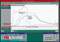
Figure 4. Graphical sequence of data from valve gate control.
Sequence for the alternate cavity control. Figures courtesy of RJG, Inc.
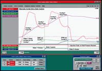
Figure 5. Alternate cavity control on a machine making two parts the size of a wheel cover for an automobile.
Typical sequence.
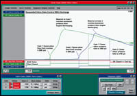
Figure 6. The cavity pressure graph for sequential valve gate control with discharge.
Another form of sequential valve gating.
In Part I of this article we discussed independent valve gate control strategies. In Part II we will cover additional valve gates strategies and how these strategies can help mold builders and molders work together to develop a mold that will provide the most consistent performance.
The mold the customer wants can run multiple parts varying in size, that make up the components of an assembly, often referred to as a family mold. All the parts of an assembly should be produced with one shot. This type of mold makes mold balance very difficult to achieve and the cold runner design is guesswork a lot of the time. Even so, mold builders are getting more requests for family molds and they need to have a strategy to present to their customers that ensures success.
Alternative Cavity Valve Gate Control
With alternate cavity valve gate control, the concept is to fill one cavity, pack it, close the valve, initiate filling of the next cavity and repeat the sequence until all cavities are filled, even if the cavity size varies. The sequence for the alternate cavity control is shown in Figure 1. Using alternate valve gate control, absolute control of flow speed, fill rate, packing and holding is optimized for each cavity. In addition, the parts with a projected area up to twice that normally used for a given clamp tonnage machine have been successfully filled and packed. This can generally be used for large projected areas such as wheel covers, seat backs, bumper fascias, etc.
The sequence in Figure 1 shows the initial gate opening to start the filling process. When the part is 90 percent filled, the injection rate is slowed down and the part is packed (using a lower velocity) to a cavity pressure set point in cavity 1. When the pressure is reached, the valve gate is closed, essentially closing off the gate and allowing holding to begin. Simultaneously with the closing of valve gate 1, gate 2 opens and injection velocity is accelerated to the filling velocity. When cavity 2 is 90 percent full, velocity is then reduced again to a packing velocity, which is used to obtain cavity pressure in cavity 2. Once this pressure is reached, the valve gate of cavity 2 is closed and injection is terminated.
This approach has been highly successful even with class A surfaces, with presses of about 65 percent the clamp force normally needed to do both simultaneously. This results in large savings in machine cost. There is a theoretical penalty of having essentially two fill times. However, the injection rate of the machine can oftentimes be the same as when filling cavities using parallel flow and in those situations, there is really no cycle time penalty. Cooling is different for each cavity, but generally this can be adjusted by fill rates, packing rates and cavity pressures, which are set independently. This allows multiple cavity molds and family molds to be run with different processing parameters in the same mold within the same cycle. There are huge savings with this approach.
Sequential Valve Gate Control
Sequential valve gate control is generally used in large, long flow parts, which are hard to pack from one central area. Figure 2 shows a typical sequence. In sequential valve gating, it is common to have an odd number of gates (generally three to five) so that flow can be initiated in the center of the part and flow radially outward. This is accomplished by opening the single gate at the start of fill and allowing the flow to extend radially outward until it passes the next set of gates. Once pressure is detected in the secondary gate areas, the valves are opened and the flow continues radially outward from the center of the part. Doing this minimizes the pressure loss in the system and eliminates knit lines, which would be present if the part was filled from each of the drops simultaneously.
Once the part is filled, the velocity of injection is reduced and all gates are left open for pack. Once the pressure is reached in the localized area, as set on the controller, the valve gate is closed to hold the plastic in the mold, or the injection pressure is terminated and the cavity is discharged until the cavity pressure set point is reached. Both of these techniques allow different types of packing and holding to be initiated, which is dictated by the specific geometry of the part.
Another form of sequential valve gating is shown in Figure 3. In this situation, the cavity is filled from one end to the other. The initial gate is opened at one end and as the flow progresses; cavity pressure sensors control the opening sequence for the remainder of the gates. Once all the gates have closed packing occurs. In all cases the sequence configuration is dictated by part geometry.
Opportunities
Sometimes during a mold tryout the new mold doesn't exactly fit in the tryout machine. Valve gate strategies provide an opportunity for the mold builder to utilize a strategy to fit a mold in a molding machine—eliminating the need to perform the tryout at another location due to size constraints of the machine. Using the valve gate control scenario opens up many opportunities for cost savings for the molder and hopefully offsets the increased cost of the mold. The largest cost savings is with alternate cavity control, because clamp tonnage of the machine used for a given mold can generally be reduced significantly without resorting to stack molds. However, the major savings in all of these scenarios is that unparalleled part consistency can be achieved over long periods of time due to independent control of flow fronts. This is true even with normal viscosity variations in the material. Inspection time of Class A surfaces can be reduced and the control of flash, sinks, short shots, knit lines and warp can all be made more consistent with the use of sequential valve gate control.
Cautions
It is important to understand when doing mold sampling or utilizing valve gates to control flow fronts, that sensor information is highly robust so that the proper sequencing is always assured to eliminate over packing of a mold. It is critical that an automated sensor check during each cycle be employed to ensure that each sensor has the capability of performing in highly critical applications, and that redundant sensors are in use for fail safe and backup precautions. Abort strategies should be implemented in the control strategy.
The Graphical Sequence
The graphical sequence of data from valve gate control is shown in Figure 4 for independent valve gate control. The red line in the graph is the plastic pressure of the molding machine. The green and the blue are different cavities in the same mold equipped with valve gates.
In this case, the cavity depicted by the green graph (cavity 12) shows filling happening faster than in cavity 32, and packing also proceeds earlier in cavity 12. The cavity pressure set point for gate 12 is set at 10,000 psi. When this is reached the gate is closed at the first vertical dotted line.
The pressure in the cavity begins to decrease while the cavity pressure in cavity 32 continues to build. When the pressure reaches 8,500 psi in cavity 32, that gate is closed and injection forward is terminated. Because all gates are closed, we see that the cavity pressure is then maintained until the start of screw run, at which time the valves are opened to allow discharge to occur during cooling.
The valve gate sequence is shown on the bottom of the cycle graph. The set points and the status are shown on the bottom left and the sequence of the machine is shown on the bottom right.
Figure 5 shows alternate cavity control on a machine making two parts the size of a wheel cover for an automobile. The graph shows the plastic pressure in the barrel builds up rapidly and we see a fast fill as depicted on the screw volume graph labeled “cavity 1 fast fill”. At the point where the cavity is approximately 90 percent filled, the machine is transferred to a low velocity as depicted by a change in slope of the volume injection graph labeled “Cavity 1 Slow Pack”.
The first vertical dotted line (green) shows the termination of packing of cavity 1 at 2,900 psi in the cavity, which is when valve one closes and valve gate 2 is opened. When this occurs, the machine is accelerated back into a cavity 2 fast fill mode and then cavity 2 slow pack mode until the cavity pressure of 2,700 psi is reached in cavity 2. At that point the valve gate closes, the injection forward is terminated and no holding pressure is needed as depicted on the curve.
Sequential Valve Gate Control with Discharge
Figure 6 shows the cavity pressure graph for sequential valve gate control with discharge. In this situation, the injection starts through a center, non-valve gated drop with both valve gates closed. Valve gate 1 opens approximately 1-1/2 seconds into the cycle when the flow front reaches 500 psi and then the flow begins through gate 1. Valve gate 2 opens when the flow front reaches 500 psi. Valve gate 1 closes when the pressure has fallen to 3,300 psi. Material at gate 2 reaches the maximum pressure and begins declining and gate 2 closes when the pressure falls to 2,700 psi. In this scenario, the discharge is used to minimize compressive stress in the valve gate areas and to minimize warp while eliminating knit lines in the part.
Mold Design Considerations
As this article's title suggests the central point is that new control techniques require individual control of each valve gate. The moldmaker should take into account a number of factors that may not have seemed significant in valve gate systems in which all gates open and close at the same time. Most of these considerations are dictated by the need for quick, accurate response in controlling cavity pressure using valve gates. Some of these are as follows:
- Ensure that the valve cylinder area to valve pin area ratio is large enough that, given the available pressure, each gate can close against the highest expected cavity pressure.
- Ensure that there will be sufficient flow in the system to open and close the gates quickly.
- If accumulators are used to achieve the neces-sary flow, ensure that they can recharge sufficiently before the next valve gate cycling is required.
- Carefully document the plumb-ing, fittings and cavity pressure sensors so that when the mold is run, the gates get properly plumbed to their individual driving solenoid valves.
- Compactly bundle or bury sensor cables and air valve plumbing to keep these connections from getting damaged.
- In alternate cavity applications ensure that the residual pressure in the cavities first completed, is added to the pressure in the second set of cavities when computing maximum required clamp force.
Summary
Sequential valve gate control of individual flow fronts in injection molding is a technology that has recently matured into a more sophisticated tool. This allows the precise individual control of melt flow fronts, the use of cavity pressure sensing, along with a sophisticated control of fail safe sensor capability and flexibility in terms of how the valve gates can be sequenced. This is the key to a robust system. Tying this to a networked production system, which allows machine independent setups of these complex tools, can be a key to maximizing uptime, process capability and performance, especially on large machines with complex processes using hot runner valve gates.
These strategies take the capability of the toolmaker to a new level, allowing him to meet the molders' and OEMs' requests for strategic processing and utilizing one mold to do more (lean moldmaking and lean manufacturing).


Related Content

How to Eliminate Chatter
Here are techniques commonly used to combat chatter and guidelines to establish a foundation for optimizing the moldmaking process.
Read More
Plastic Prototypes Using Silicone Rubber Molds
How-to, step-by-step instructions that take you from making the master pattern to making the mold and casting the plastic parts.
Read More
The Benefits of Hand Scraping
Accuracy and flatness are two benefits of hand scraping that help improve machine loop stiffness, workpiece surface finish and component geometry.
Read More
Considerations for Mold Base Material Selection
Choosing the right material can greatly affect the profitability and cost of your application.
Read MoreRead Next

Part One of a Two-Part Series Valve Gate Sequencing Strategies
Ways to use valve gate control strategies to improve quality, efficiency and profitability
Read More
How to Use Strategic Planning Tools, Data to Manage the Human Side of Business
Q&A with Marion Wells, MMT EAB member and founder of Human Asset Management.
Read More
How to Use Continuing Education to Remain Competitive in Moldmaking
Continued training helps moldmakers make tooling decisions and properly use the latest cutting tool to efficiently machine high-quality molds.
Read More