Integrating Rapid Prototyping With the Shop Floor
The CNC-based RP process works to complement existing production techniques.
Share
Rapid prototyping (RP) technologies have revolutionized much of the prototyping industry in the last couple of decades. Unfortunately the capital, space and technical requirements have left many traditional machine shops with-out the ability to compete with these new RP technologies. Machining still beats RP with accuracy, cost, speed, robustness and other advantages. The principal advantage of RP has been the geometry capabilities.
Finally a new technology, CNC-based RP has arrived that will allow RP to be performed on standard multi-axis CNC milling machine machines. Overhangs, undercuts, hollows and internal geometries are all automatically handled by this new approach to CNC machining. This CNC-based RP solution works with the industry standard CAD solid model STL file format, existing CAM software and with existing CNC milling machines to provide a RP result. The key is intelligent software that can split CAD solids into a series of operations, coupled with iterating between depositing and machining materials.
The example described in this paper uses a sample part to describe this new approach to RP by traditional machining tools.
Process Overview
Start by importing a CAD solid model in the STL format into a new software program that automatically divides the solid model into sets of surfaces, which can be incrementally created on a CNC milling machine. These surfaces are output to a standard CAM program to generate toolpaths for each surface. The 3-D part is built by alternating between depositing volumes of material and machining surfaces. The part is never repositioned during this process, instead the additive process of depositing more material allows for overhanging geometries to be created. After each deposition process the next surface is machined, adding up to the finished part. This unique process allows standard milling machines to handle difficult overhangs, interior volumes and other geometries traditionally considered difficult or impossible. The new software program makes all of the geometry-based decisions, while the operators continue to perform their standard CAM and machining functions.
Materials
The CNC-based RP process requires that a minimum of two materials be used during the construction process. One functions as a temporary mold, the other material forms the finished part.
The temporary mold is used to support and cast features into the part during construction. This material is deposited and shaped by conventional, subtractive, machine tool techniques to form a mold for all the overhanging features of a part.
The construction material is used to form the finished part. This material also is deposited and shaped by conventional, subtractive, machine tool techniques to form all the upward facing features of the part. The two materials must be compatible such that the removal of the mold will not compromise the finished part.
Many materials can be used with this process and good results have been achieved with standard off-the-shelf products. For example, much work has been done with polyurethanes and aluminum filled urethanes—materials that are easily acquired, cost-effective and simple to use.
The preferred material used as a temp-orary mold is a fusable alloy of indium. This is a special metal alloy with the unique characteristics of melting below the boiling point of water, having extremely low volumetric change during phase changes and being easily machinable.
Immersing the finished object in a hot water bath facilitates removal of the temporary mold. The high density of the alloy allows it to fall to the bottom of the water bath, separating from the finished part and ready to reuse. The machining chaff also can be recycled in this same manner, with contaminants being removed automatically due to the difference in density or, in the case of metallic contaminants, filtered.
Example
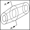
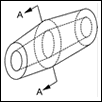
The production of an example part is described in this section. In Figure 1 a 3-D part is represented. This part can be described as a thick wall tube with a flared center section. In subsequent figures the part will be viewed in section as shown by the line A-A.
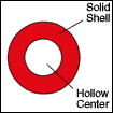
Figure 2 shows the cross-section A-A of the part in Figure 1. The solid wall of the tube is shown as being shaded. For physical reference, this part will be constructed with the portion of the tube wall shown in Figure 2 closest to the bottom of the page being at the lowest elevation during construction. The portion of the tube wall shown in Figure 2 closest to the top of the page will be at the highest elevation during construction.
The representation of the mold and construction materials is as shown in Figure 3. After the operations are completed the mold material is removed.
To begin the construction of this part, first deposit a base of the mold material as shown in blue in Figure 4. The lines show the outline of the desired part.
With the first volume of metallic mold material deposited and solidified, the first toolpath is run, creating the first surface. The resulting machined volume of metallic mold material forms a mold for the deposition of the construction material. Figure 5 shows the machined mold material and lines representing the outline of the desired part.
The metallic mold material, with sculpted features, is covered with a volume of construction material, shown in red in Figure 6. The construction material flows into the sculpted surface of the mold material, molding these features into this volume of construction material.
With the volume of construction material deposited and solidified, the construction material is milled automatically. The underside features of the part have had details cast in during the deposition process. Machining of the topside is done after the construction material has fully solidified. The resulting machined volume of construction material forms a portion of the finished part. Figure 7 shows the machined construction material and lines representing the outline of the desired part.
The construction material, with sculpted features, is next covered with another volume of metallic mold material. The previously molded and sculpted volume of construction material is now completely encapsulated, as seen in Figure 8.
After the metallic mold material has been deposited and has solidified over the previous volumes of mold and construction material, the mold material is again milled. The resulting machined volume of metallic mold material forms a mold for the deposition of the next volume of construction material, which can be seen in Figure 9.
The previous volume of metallic mold material and construction material, with sculpted features, is covered with a volume of construction material as seen in Figure 10. The construction material flows into the sculpted surfaces, molding these features into the underside of this volume of construction material.
With the volume of construction material deposited and solidified, the construction material is milled. In this example, this concludes the necessary steps to form the desired part out of construction material (see Figure 11).
Removal of the remaining metallic mold material is accomplished by placing the part in a hot water bath; the metallic mold material melts below the boiling point of water. With the metallic mold material being much heavier than the surrounding water and the finished part, it is easily separated and falls to the bottom of the bath. An added advantage of the metallic mold material is that it can be reused in the process, even the machining chaff can be scooped up and melted in the water bath. The finished part is shown in Figure 12 and Figure 13.
The same basic steps as shown in this example can be used to make any geometry of part.
Benefits
CNC-based RP provides benefits that no other RP technology can approach. The ability to use existing shop floor equipment allows the user to operate relatively inexpensive equipment that is robust and accurate. CNC milling equipment has been in commercial use for decades; there are no expensive lasers to be replaced, complex material handling systems or high-tech maintenance packages. CNC equipment is proven, reliable technology.
Part size is extremely flexible. CNC-based RP is not restricted in part size, CNC mills are commonly available from a few inches (centimeters) to yards (meters) in length on each axis.
Speed is adjustable. CNC-based RP is not limited by the cure rate of a photopolymer or the droplet rate of an inkjet. The rate is a function of the speed at which you remove material. The bigger the mill and the more powerful the spindle motor, the faster you produce parts.
Many different materials are under investigation for use with CNC-based RP. The ability to use a wide variety of different materials allows for flexibility in application of the software. Parts have been produced from thermosetting plastics, thermoplastics, waxes, ceramics and composites.
Costs associated with CNC-based RP are much less than other RP techniques. Because CNC-based RP is free from dedicated equipment, the initial purchase cost is a fraction of other systems. Raw material cost can be kept low due to the nature of the process. The metallic mold material is reusable and thereby vastly reduces the cost of production. Because materials are not deposited by a precision extrusion nozzle or ink jet mechanism there is no concern over clogged nozzles or expensive replacement parts.
Continuing costs—such as laser replacements and machine service contracts—are not necessary with CNC-based RP. CNC milling machines are generally rugged, reliable and easily repaired. CNC-based RP does not require site visits by authorized company service technicians or machine service maintenance contracts.
Conclusion
CNC-based RP provides excellent value by using standard commercial off-the-shelf equipment and materials. Shops across a wide variety of industries can produce prototypes and short-run parts economically and accurately. Rather than trying to adapt traditional production technologies to the limitations of existing RP, the CNC-based RP process works to complement existing production techniques.
Related Content
Leading Mold Manufacturers Share Best Practices for Improving Efficiency
Precise Tooling Solutions, X-Cell Tool and Mold, M&M Tool and Mold, Ameritech Die & Mold, and Cavalier Tool & Manufacturing, sit down for a fast-paced Q&A focused on strategies for improving efficiencies across their operations.
Read MoreThe In's and Out's of Ballbar Calibration
This machine tool diagnostic device allows the detection of errors noticeable only while machine tools are in motion.
Read MoreControl Helps Push the Limits of Five-Axis Micro Mold Machining Accuracy
Toolmaker quickly meets the demands of critical medical device manufacturers with a new five-axis machine tool equipped with the right control technology.
Read More3D Printing Enables Better Coolant Delivery in Milling Operations
Just like 3D printing enabled conformal cooling channels in molds, additive manufacturing is now being used to optimize coolant delivery in cutting tools.
Read MoreRead Next
Rapid Prototyping Is About Tool Design, Process, Materials, Manufacturability and Costs
To have a high level of assurance that prototypes will simulate production output and production processes, they have to be formed using tool designs, materials and machines that approximate high-volume manufacturing.
Read MoreAre You a Moldmaker Considering 3D Printing? Consider the 3D Printing Workshop at NPE2024
Presentations will cover 3D printing for mold tooling, material innovation, product development, bridge production and full-scale, high-volume additive manufacturing.
Read MoreHow to Use Continuing Education to Remain Competitive in Moldmaking
Continued training helps moldmakers make tooling decisions and properly use the latest cutting tool to efficiently machine high-quality molds.
Read More






.jpg;maxWidth=300;quality=90)


_300x250 3.png;maxWidth=300;quality=90)


