
Selecting a Carbide End Mill for Aluminum Applications
Specific geometries and characteristics of a carbide end mill are required for efficient machining of aluminum.


Mold shops are currently seeing an increase in jobs where customers specify aluminum instead of traditional mold steels, such as P20 and H13. Aluminum alloys offer many advantages for molding, such as good thermal conductivity, lightweight with high strength-to-weight ratio and excellent machinabilty. For this article, we will focus on machinability.
By using carbide end mills with the correct cutting geometries and coatings, metal removal rates can increase by four to five times — or higher — than that of mold steel. Surface finishes of 16µ or better are also easily achieved, reducing mold finishing time considerably.


The results are not quite as strong with long-edge indexable end mills, which will always leave a slight mismatch line between insert rows. Insert pockets are machined into indexable cutter bodies one at a time. Helical cutting edges on a solid carbide end mill are ground in a continuous grinding operation.
Requirements for Efficient Machining of Aluminum
Due to the soft and “sticky” nature of aluminum, specific geometries and characteristics of a carbide end mill are required for efficient machining. Many cutting tool manufacturers offer end mills specifically designed for aluminum for this reason.
A sharp edge and high rake angles are needed to separate a chip from the parent material. Positive rake angles up to 25 degrees radial and 20 degrees axial are common.
A high helix angle, generally around 45 degrees is also desirable. The helix helps move chips up and out of the cutting zone and also generates an excellent surface finish. The angle also helps soften the impact at entrance of cut, resulting in a smoother, quieter cut (see Figure 1).
Figure 1. Key end mill geometries. Figures courtesy of Guhring.
For aluminum milling a two- or three-flute end mill works best because this allows for larger flute areas. A core diameter of slightly less than 50 percent of cutter diameter is optimum for the same reason. An open flute design is essential for easy chip movement away from the cutting zone. Surface finish on the flute is also critical. Long-chipping, low silicon aluminum alloys have a tendency to stick to cutting tools. As a heated chip flows over the flute it will try to adhere to the tool surface. The flute surface must be very smooth to counteract this tendency.
Extremely slick commercial tool coatings are also available that reduce the friction coefficient on the flute surface. A good example is one that has a friction coefficient of 0.1, less than half that of TiCN.
Coolant is important for chip evacuation and keeping the tool cool. Common choices include using flood coolant or an air gun with mist coolant. Flood coolant with high enough pressure to move chips out of the way is preferable, especially if using an uncoated tool. When using a coated tool, the air gun with mist coolant is often all that is needed.
When chip management becomes a problem, consider using a coolant-through end mill. Coolant ducts exit in the flute area and help move chips out of the cutting zone. Roughing tooth profiles are also helpful in reducing the size of the chip, making it easier to manage and blow out of the way.
All of these elements help reduce the probability of built up edge (BUE), a common failure mode when a general-purpose end mill is used in aluminum machining. BUE is the accumulation of workpiece material on the cutting edge. Once this occurs, the cutting action becomes a tearing action. Surface finish drops immediately, and spindle load will increase dramatically. If you are cutting a full width slot, tool breakage is most likely to happen before you can get to the feed hold control (see Figure 2).
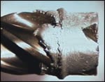
Figure 2. The result of a poor end mill choice for an aluminum application. The tight flutes and low rake angles of this end mill do not allow good chip flow, and the aluminum chips quickly packed into the flutes of the mill. Not only is the tool destroyed, but the workpiece surface as well.
Whenever possible, try to avoid using a dead sharp corner. Sharp corners tend to break down quickly. Using a corner radius or chamfer type end mill will increase tool life.
Putting It into Practice
Now we are ready to machine a mold plate and really make time. If you are to take maximum advantage of high-speed machining of aluminum, it is important to have the right machine for the job. Your machining center will ideally have spindle capabilities up to 18,000 rpm and feed-rates of 200 ipm.
For peripheral rough milling, the following feeds and speeds will work well as a starting point. For aluminum alloy (2024, 7075, 6061, etc.), try the following: climb mill with a ½" diameter three-flute coated carbide end mill for aluminum. Take a width-of-cut (WOC) of 30% of cutter diameter or 0.150", axial depth-of-cut .750", sfm 2,000, rpm 15,280, ipt 0.004, ipm 200 (This value adjusted for radial chip thinning.). Machining at these parameters will result in a metal removal rate of 22.5 cubic inches/minute, impressive for a ½" diameter end mill.
For full width slotting a two-flute end mill is recommended. You can plunge in Z up to 1 x diameter before moving in X-Y or better yet try ramping into the desired depth. Run at sfm 1,000, rpm 7,640, ipt .003, ipm 46. The metal removal rate will be 11.5 cubic inches/minute, half of the peripheral milling example above. However, once the slot is in, be sure to program feeds and speeds for peripheral milling again to open up the cavity.
Three Key Points
Choosing and applying the correct carbide end mill will result in substantial time savings for your shop. Three key things to remember are:
- Use an end mill specifically designed for aluminum machining.
- Use a machine with high speed and feed capabilities.
- Be sure to evacuate chips from the cutting zone.
Chances are your competitors are using these techniques; you can too.


Related Content

Considerations for Mold Base Material Selection
Choosing the right material can greatly affect the profitability and cost of your application.
Read MoreExploring ISO 9000 - Part 16 Control of Quality Records
A Series of International Standards for Quality Management and Quality Assurance. We begin 2022 with a review of Clause 4.16 Control of Quality Records.
Read More
How to Correctly Size a Hydraulic Cylinder
This week Randy shares steps for correctly sizing a hydraulic cylinder on a mold.
Read More
How to Eliminate Chatter
Here are techniques commonly used to combat chatter and guidelines to establish a foundation for optimizing the moldmaking process.
Read MoreRead Next

The Key to Controlling Your Machining Process
Controlling heat is the most important factor in high-speed and hard metal machining.
Read More
Part One of a Three-Part Series Five Steps for Improving Your Shop’s Maximum Productivity
Learn how to evaluate your shop’s productivity and begin increasing it by considering the variables of implementing hard milling and high-speed machining.
Read More
What To Consider When Thinking About Solid Carbide End Mill Machining
The selection of geometries and coating for solid carbide end mills can be a confusing, but evaluating the operation will determine which end mills are best for the job.
Read More