
Cut the Chatter - Tooling Tips to Eliminate Vibration in Cavity Milling
By learning how to eliminate vibration in cavity milling operations, a typical moldmaking shop can decrease the wear and tear on its tools, as well as boost its level of productivity.


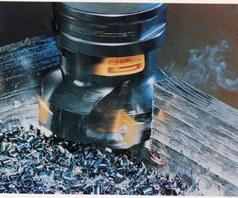
Figure 1: Cutting tool specifiers can reduce overall cutting force and resulting vibration by using positive rake inserts shown on this cutter. The shearing action of positive rake cutters reduces cutting forces by more than 20 percent versus zero- or negative-rake milling tools.

Chart I: Insert shape influences vibration by altering the entry angle of the cutting edge to work. Rounds are most prone to vibrations, 45-degree lead angles are the least. In addition to insert shape, users seeking to minimize vibration should consider inserts protected by thinner PVD coatings.

Figure 2: Rigid couplings in modular tooling will reduce vibration. In one modular tooling system, the couplings feature 100 percent contact area between the components for rigidity and even distribution of torque.
Figure 3: This hydromechanical chuck grips the tool firmly in place without slippage, resulting in excellent tool balance. It offers two to three times the clamping force of traditional types and permits 20-second tool changes.
Eliminating chatter or noisy vibration in moldmaking and other cavity milling operations pays off in greater productivity. It increases metal removal rates, enhances surface finishes with fewer finishing steps and reduces scrap.
Eliminating vibration also reduces wear on cutting tools and machining centers to minimize machine downtime. Poor fixturing, workholding and machine maintenance all contribute to vibration and its associated problems. The best way to quiet chatter is often a combination of remedies. However, machine operators and manufacturing engineers generally look first at their cutting tools. A knowledgeable supplier of both segmented and solid carbide cutting tools can integrate total solutions to stop the chatter.


Vibration in cavity milling creates uneven wear on cutting tools and shortens tool life. While indexable insert milling cutters and solid carbide endmills differ in construction, they are both vulnerable to chatter and share some common vibration remedies. Indexable insert milling cutters are generally available in diameters down to one-half inch. They use replaceable inserts with a choice of geometries and coatings. Smaller openings call for solid carbide endmills with two, three or four cutting edges. There are steps that users can take to end vibration with both milling cutters and endmills.
Milling Cutter Chatter
Use cutters with fewer inserts. Although it may seem counterintuitive, the first step to reducing chatter in milling operations is to switch to a cutter with fewer teeth. In general, the coarser the cutter pitch, the lesser the chance of harmonic vibration. Sometimes, replacing a 16-tooth cutter with a 12-tooth tool ends chatter altogether. A differential-pitch cutter may be required in more difficult cases to eliminate troublesome harmonics.
The larger the cutter, the better the performance will be. Conditions permitting, larger cutters provide more choices about how to approach the workpiece. Varying the relative position often helps damp vibration. Manufacturing engineers should try to keep the cutter diameter 20 to 50 percent larger than the width of the cut. The cutter should be sized so that no more than two-thirds of the inserts are engaged in the cut at any time. These guidelines help produce an ideal entry angle, thereby reducing cutting forces and vibration.
Optimize insert geometry. The shape of the cutting inserts often determines their vibration tendency. Round inserts are most vibration prone, while those with 45-degree lead angles are the least prone to chatter. The smaller the entry angle of the cutting edge to the work, the lower the tendency to vibrate. Chart 1 ranks the various insert shapes for vibration tendency.
Cutting tool specifiers can reduce overall cutting force and resulting vibration by using positive rake insert geometry. The shearing action of positive rake cutters reduces cutting pressure by more than 20 percent versus zero- or negative-rake milling tools (see Figure 1). The sharper edge and angle of entry of this type of insert also helps to reduce the power needed to penetrate the surface of the workpiece.
Choose insert coatings carefully. Coatings on inserts perform many functions, but their primary jobs are protecting against heat, maintaining lubricity and preventing build-up on the insert. To reduce edge rounding and chatter, you should look to replace inserts protected by thick CVD coatings with those wearing thinner PVD coatings. Though CVD treatments are formulated for wear resistance, PVD coatings provide a sharper insert edge and a more positive rake angle to help minimize vibration.
Stiffer Tools, Less Vibration
The same anti-vibration principles true for indexable milling cutters also apply to solid endmills. To reduce vibration, users should select endmills with fewer teeth and a high helix. A steeper helix corresponds to a more positive rake. A shallow helix is equivalent to a negative rake. To minimize vibration, endmill users should examine using helix angles from 30 to 60 degrees relative to the centerline of the tool.
Minimize length; maximize diameter. In addition to positive rake and high helix angles, both milling cutters and endmills should be as stiff as possible. Machine operators and manufacturing engineers should do everything possible to minimize the bending or deflection of cutting tools. A rule of thumb states that reducing the length of the tool by 20 percent reduces the amount of bending in the tool by 50 percent. Likewise, increasing the diameter of a cutting tool by 20 percent cuts deflection in half. In practical terms, this usually means that you should try to use the largest diameter tool you can to do the job.
In addition to large diameter tools, try to use the shortest tool possible for each application. Many operators tend to choose a tool that meets the most demanding case on a workpiece requiring multiple operations. For a workpiece with several hole depths, the same long tool selected to make the deepest hole is also used to make shallower penetrations. Using a longer-than-necessary tool in shallow holes contributes instability to the entire operation and invites chatter. Programming the machine to use the right tool for each step minimizes vibration and maximizes productivity for the entire job.
Feeds, Speeds and Angles
Maintain feed pressure per tooth. To minimize vibration, don't try to go easy on tools by reducing feed pressure. Too light a feed allows the tool to slip and is just as prone to generate vibration as too heavy a feed pressure. Use the loading recommended by the tool supplier to minimize chatter and maximize tool life.
Increase feed rate. Machine operators commonly respond to a vibration problem by reducing the cutting speed and leaving the table feed alone. Speeding up the machine or the feed may seem like a recipe for disaster. However, an increase in feed at the same rpm may turn out to be the ideal solution. Anyone who has experienced harmonic vibrations in a car on the highway knows either speeding up or slowing down can end the noise. Similar experimentation can counter the complex harmonics of milling chatter.
Vary entry points. Moving the centerline of the cutter slightly to either side of the entry point on the workpiece can often reduce the tendency to chatter or vibrate. The offset creates a finer entry angle and prevents forces from oscillating from one side of the cutter to the other. For a two- to three-inch facemill, the offset may be 3/16". For a one-inch endmill, the offset may be 0.0050". Again, experimentation can determine the low-vibration setting.
Toolholding Options
Balance and true cutting tools. Cavity milling operators seeking to minimize vibration should make sure that their tool is properly balanced and that it is mounted true to the spindle center. Strategies for connecting the tool to the machining center vary widely. Especially on milling jobs with long overhang, machine operators should avoid toolholders that rely only on setscrews or keyways to transmission of torque. Modern toolholding solutions, like a modular toolholding system, can help ensure balance and true mounting (see Figure 2).
One system reduces tool runout to less than eighty millionths of an inch. The holder design maintains 100 percent contact in the clamping area where torque is transmitted to the tool. For shanked tools, a hydromechanical chuck improves tool balance and stability, and thereby reduces uncontrolled vibration (see Figure 3).
Integrated Solution
Chatter is the product of every element in the cavity milling process, including the tools, the machine and the workpiece. The total system remedy is to eliminate all vibration sources that can lead to harmonic responses. Run the job on the "tightest" machine available. The more that the machine's ways and spindle are tight and robust, the less vibration will occur. Keep the structure rigid from spindle to cutting edge. Clamp the part to minimize movement, vibration and deflection. Add support close to the areas to be machined.
Vibration is most likely in workpieces with a long overhang. As a rule of thumb, whenever a cutter's shank aspect ratio - its length-to-diameter ratio - exceeds three to one, the risk of vibration rises rapidly. With ratios over five to one, vibration-damping adapters/extenders and modular toolholders can help. Unlike solid adapters that transmit vibrations readily, today's vibration-damping adapters have an internal chamber containing a heavy body suspended on rubber bushings. Machine operators should position the milling cutter as close to the tuned adapter as possible.
Tooling is just one element in the campaign against vibration. If none of these remedies work in your particular case, ask your tooling supplier for recommendations on your machine, your workpiece and your procedures. A knowledgeable supplier can provide insight into vibration problems and cut the chatter.


Related Content

New Innovations in Mold Design, Milling Cutters, 3D Scanning
MoldMaking Technology compiles a number of digital-only products from the past month, including mold design software, laser metrology 3D scanners, milling cutters and more.
Read More
Ten Things You Need to Know about Circle Segment Milling
Considerations for evaluating if circle segment end mills or conical barrel cutters are right for your mold machining applications.
Read More
MoldMaking Technology's Most-Viewed Content 2022: Products
MMT shares the five top-viewed technologies, equipment and services of 2022 in each Engineer, Build, Maintain and Manage tenet based on Google Analytics.
Read More
Tolerancing in Mold Design, Overcoming Cutting Tool Vibration, SPE MTD Updates & More Most-Viewed May Content
Every month, MMT draws inspiration from its diverse readership's wide-ranging interests, from mold design tolerancing to cutting tools and beyond. Here are May’s top 10 most-viewed articles, based on Google Analytics.
Read MoreRead Next

How to Use Strategic Planning Tools, Data to Manage the Human Side of Business
Q&A with Marion Wells, MMT EAB member and founder of Human Asset Management.
Read More
Reasons to Use Fiber Lasers for Mold Cleaning
Fiber lasers offer a simplicity, speed, control and portability, minimizing mold cleaning risks.
Read More
Are You a Moldmaker Considering 3D Printing? Consider the 3D Printing Workshop at NPE2024
Presentations will cover 3D printing for mold tooling, material innovation, product development, bridge production and full-scale, high-volume additive manufacturing.
Read More