
A New Approach to Designing Lifter Cores: Dual-Rod Design
Benefits of using a secondary guide rod on lifter core assemblies.


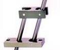
A dual-rod system. Photo courtesy of D-M-E Company.
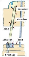
Figure 1: Problems often experienced with single-rod lifter systems. Figure courtesy of Takao Injection Mold Engineering Co., Ltd., 2004.
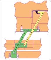
Figure 2: Example of a preferred embodiment for designing a lifter core assembly. A second guide rod is used to create a parallelogram that significantly reduces moments acting on the lifter rod. Figure courtesy of Takao Injection Mold Engineering Co., Ltd., 2004.
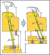
Figure 4: Example of lifter core assemblies with internal cooling features. This example also shows how two slide base assemblies may be “ganged” together to actuate and support a single large lifter core. Figure courtesy of D-M-E Company.
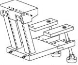
Figure 3: Reduction in bending stress in lifter rod allows for larger angle, thereby reducing die height. Figure courtesy of Takao Injection Mold Engineering Co., Ltd., 2004.
Conventional lifter cores have been somewhat limited in their performance given the large mold footprints they create. Reactionary forces and bending moments within conventional lifter core rods require smaller rod angles, which can increase mold die height and footprint.
A new approach to designing lifter cores utilizes a second guide rod that is parallel to the lifter rod. This formation eliminates the bending moment seen in conventional single-rod lifter configurations, allowing for a greater lifter angle and reducing overall die height and mold footprint.


This article analyzes both single- and dual-rod lifter systems and the benefits, limitations and applications of each. We’ll also look at how to build a second guide rod into a mold.
Single-Rod Lifter Systems
When designing mold cores for undercuts and side-action molding, the designer has several lifter system options. The first is using sliding cores and angle pins. This option requires considerable mold space and may result in selecting a lifting core with a smaller platen size at the expense of a larger die height.
Conventional lifter cores also have limits on the angles allowed. If the molded undercut is large, the mold footprint may need to be increased to accommodate the required side travel of the lifter core, increasing the required die height even further.
The single-rod lifter system is designed with the core, sliding plate and gib plates within the ejector plate assembly. Close alignment of the core is accomplished through tight tolerance entrance and exit holes in the core plate. This results in additional cost and added processing problems. An overriding problem of the conventional configuration: bending moment acting on the lifter rod, which leads to increased friction, abrasion and side loads (see Figure 1).
If the lifter rod is not sized properly, premature wear or even breakage can result. Therefore, designers often over-design the lifter rod to account for additional loading. This increases component costs and limits the number of applications for the lifter mechanism.
Dual-Rod Lifter Systems
Use of a second guide rod parallel to the lifter core is a relatively new and under-utilized method. The additional guide rod ensures proper alignment of the sliding base within the ejector plates. It also eliminates the bending stresses that occur as a result of the typical load distribution described within the conventional setup.
The new configuration creates a parallelogram within the ejector plate assembly between the primary lifter core, secondary alignment rod, alignment plate and sliding alignment base, as shown in Figure 2. The structurally sound parallelogram eliminates the bending moment that occurs in single-rod systems.
The use of a fixed secondary pin eliminates friction between the secondary pin and the upper alignment plate. The actuating load transferred to the primary lifter core is now centered on the axis of the lifter core and in the same direction as the motion of the core. The reduction in friction and bending moment permits a greater lifter angle, allowing the designer to reduce both the necessary die height and the mold footprint on the platen (see Figure 3).
How to Incorporate Dual-Rod Technology
As shown in Figure 2, an ejector housing cross-section must be designed with the desired plate thickness and necessary ejector stroke. By increasing the lifter core angle, a mold designer can achieve faster part ejection and a larger undercut feature. A guide plate is used to retain the second guide rod, as well as align the lifter core rod. Sufficient space around the lifter core rod is needed when placing and sizing the guide plate. Starting from the retaining feature for the guide rod in the guide plate (in this case, a dowel), a line parallel to the centerline of the lifter core rod should be drawn into place.
Ideally, standard components for these lifter systems will be developed ensuring all guide rods feature a round design, as opposed to one with a rectangular cross-section. A sliding assembly, such as a block base, may be used to reciprocate along the plane of the ejector plate assembly as the machine’s ejector rod moves though the extent of the ejector stroke. Both the primary lifter core rod and the second guide rod are aligned and retained by the sliding base within the ejector plate assembly.
Since the second guide rod must not move, it is retained further down in the base of the ejector box assembly, as seen in Figure 2. To retain the second guide rod, use a pivoting guide bushing, held in with a pin to the sliding plate. Since the loads acting on the pin are minimal, the pin can be small.
Next, the lifter core must be physically connected to the sliding plate. A mold designer has several options, each with different benefits. If the anticipated loads acting axially on the lifter core will be excessive (the weight of the lifter core itself may even qualify as excessive), then making a tapered surface cut into the sliding plate will enable sufficient backup and support behind the lifter core rod.
If the expected axial load in the lifter core rod is moderate to low, then a pin or similar device is sufficient to retain the lifter core rod. Mold designers should note, however, that the strength of the assembly will be that of the weakest link; in this case, the joint pins retaining the lifter core rod. Make sure the joint pin and the overall lifter are sized accordingly.
In the final stages of lifter system design, the mold designer adds clearances for the slot used to retain the sliding plate, as well as clearances for the guide and lifter core rods. Use of a guide plate, slide plate and base-mounted retainer bushing eliminates the need of machining tightly toleranced, angled holes into the mold plates themselves.
By using a pivoting guide bushing with sufficient close-fit tolerance to the guide rod, in combination with a loose-fit installation on the base-mounted retainer bushing, the guide rod and sliding base assembly will effectively self-align. When the assembly technician is satisfied that the ejector plate assembly and lifter core system all move freely, the base-mounted retainer bushing can finally be bolted in place, providing the necessary guide rod retention for normal use.
Another benefit to the sliding base design is the rigid backup to the lifter core rod, which allows the use of lifter core cooling (provided the lifter core rod and overall assembly is large enough to accommodate the diametrical size of the intended waterlines, seals and fittings without affecting the lifter rod rigidity required to move the intended lifter core mass). Refer to Figure 4 for more detail regarding the addition of cooling to the lifter core assembly.
The use of a guide rod to guide the slide base in the moving ejector plate assembly reduces stress on the lifter rod and allows for use of a smaller lifter core assembly. This also means that multiple lifter rods and the attached cores can be ganged together, and are actuated by either more or less slide base and guide rod assemblies, depending on the needs of the application. The level of flexibility and functionality offered by this approach can lead to increased competitive advantage for both the moldmaker and end user.
Many Advantages to Dual-Rod Design
Through incorporating a second guide rod in lifter core assemblies, mold designers can reduce reactionary forces in the mold and enable smaller assemblies. Without the conventional drawback of increased friction and loading due to bending moments, the dual-rod design allows deeper undercuts using steeper lifter core angles—leading to increased cost savings. The ease of design and assembly make it simple to add lifter cores to molding applications, as well as increase the molder’s capabilities when a small mold footprint is critical.


Related Content

Considerations for Mold Base Material Selection
Choosing the right material can greatly affect the profitability and cost of your application.
Read More
Solving Mold Alignment Problems with the Right Alignment Lock
Correct alignment lock selection can reduce maintenance costs and molding downtime, as well as increase part quality over the mold’s entire life.
Read More
Treatment and Disposal of Used Metalworking Fluids
With greater emphasis on fluid longevity and fluid recycling, it is important to remember that water-based metalworking fluids are “consumable” and have a finite life.
Read More
Fundamentals of Designing the Optimal Cooling System
The right mold components can help improve mold cooling and thereby produce higher-quality parts.
Read MoreRead Next

Simplifying Mold Construction
How to solve your internal thread molding problems with the right core.
Read More
How to Make “Quick-Turn” Your Shop’s Mantra
On top of increasing production capacity, quick delivery standards save as much as five hours per project for a manufacturer of quality “quick-turn” tooling.
Read More
The Advantages of New Modular Tech: Maximizing ROI and Minimizing Risk
Proven off-the-shelf modular mold components and complete component systems meet today’s demanding drive for a lean approach.
Read More