Why Choose a Valve-Gated Hot Runner?
Moldmakers need to be aware of how different gating technology can affect their customers when designing a hot runner system into a mold.
#Basics #FAQ
Share
Valve gate hot runner nozzles were introduced to the injection molding industry shortly after the first hot runner systems appeared on the market. Until recently, valve gates had been chosen primarily for applications where thermal gate vestige is unacceptable. However, valve gates offer several additional part quality and processing benefits to the injection molder including:
- Elimination of drool and gate string.
- Improved physical properties with lower molded-in stress.
- Cycle time reduction.
- Ability to balance family molds and control weld line location with sequential valve gating.
- Superior molding processes for thinwall parts.
Thermal Gating Technology
Thermal gates - commonly identified as hot tip, thermal sprue and edge gate—rely on thermal cycling of the plastic melt in the gate area for successful operation (see Figure 1). After cavity fill, the melt in the gate area cools and solidifies. Gate cooling plays a key role in how quickly solidification takes place. During the subsequent cycle, injection pressure forces the solidified gate material into the cavity, opening the gate. The small slug from the gate melts from shear heating as it enters the cavity.
Featured Content


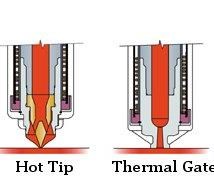
Figure 1: Thermal gating options.
A part molded with a thermal gate retains a standing vestige at the gate interface. Thermal gate vestige is highly dependent on the gate diameter. A larger gate will produce a larger vestige. Thermal gate vestige stands 1/3 to 1/2 as the height of the gate diameter. In addition, thermal gate quality can change significantly as processing conditions vary.
Gate cooling optimization is critical in thermal gate design. The solidified polymer in the gate acts as an insulating barrier between the plastic in the cavity and the viscous melt in the hot runner nozzle. Mold open cannot occur until the gate is solid enough to break cleanly from the part as well as "hold back" the melt in the hot runner. Insufficient gate cooling requires cool time greater than that required for part solidification - adding unnecessary seconds to cycle time. Mold open prior to complete gate solidification will result in drool or stringing. Excessive gate cooling also can be problematic; a frozen gate can prevent or delay gate opening. This will result in short shots or unfilled cavities.
Valve Gate Technology
Conversely, a valve gate nozzle positively seals the gate with the use of a valve stem (see Figure 2). Through mechanical action, the valve stem moves forward and seals the gate orifice. The valve stem remains in the closed position during mold open and part ejection, preventing drool and stringing. For example, Polyamide (PA) may drool when processed in a thermally gated hot runner. However, when PA is processed in a valve-gated hot runner, any potential for drooling at the gate is eliminated.
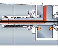
Figure 2: Valve gate assembly.
Melt decompression is often required on thermal gated systems to relieve pressure in the manifold. Valve gate nozzles eliminate the need for melt decompression because the seal is robust even if the hot runner manifold remains pressurized. Melt decompression can lead to splay and other visual imperfections.
Valve gate nozzles leave a small witness mark on the part—the same size as the gate diameter. Protrusion of the valve stem through the gate may leave a small indentation in the center of the gate. The molded part separates from the gate without breaking or shearing plastic; thus, discoloration or deformation due to gate break is unlikely. Unlike thermal systems, gate quality remains the same over a wide range of process conditions. However, one significant exception is if the valve stem is held open too long, allowing the resin in the gate to solidify; in this case, the solid plastic can prevent the valve stem from seating in the gate orifice, leaving a post.
Physical properties of the molded part are improved with the use of a valve gate. Molded-in stress is a result of molecular orientation, which is caused by shear. Valve gates, due to the larger gate diameters, generate less shear compared to thermal gates. The result is a part with less warpage and better physical properties.
Cycle Time Reduction
In addition to the cosmetic advantages, valve gate nozzles can reduce cycle time, especially when molding large parts. Hold time can be reduced with a valve gate nozzle and melt plastication can begin as soon as the valve gate is closed. In contrast, thermally gated molds must have a sufficiently frozen gate before hold pressure can be released and screw recovery begins. This difference can add several seconds to the cycle time for thermally gated parts with large gates. Also, the valve gate's lower shear rate in the gate area minimizes shear heating of the melt - reducing the part's cooling requirements.
Sequential Valve Gating
Sequential valve gating is the independent control of valve gates in a mold. Sequential valve gating is used to control the filling of parts with dissimilar mass (i.e., family molds). Each valve gate is independently opened and closed at a pre-determined event (time, screw position, cavity pressure, etc.), providing complete control of cavity fill. The balanced flow to each cavity eliminates over-packing and flash.
Sequential valve gating also can be used to control the location of weldlines or, with cascade filling, eliminate the flowlines on long parts. Weldline control is very important in parts that contain a "living hinge." The working life of a living hinge is greatly reduced if a weldline forms over the thin section of the hinge. Sequential gating can be use to ensure that the weld is positioned away from the hinge area, improving the product's performance.
Thinwall Molding
Valve gate nozzles can be especially useful for thinwall molding. Rapid fill rates, high pressures and fast cooling characterize thinwall molding applications. Rapid fill rates - in the range of 0.5 seconds or less - are necessary to fill the cavity before the frozen layer thickens and prevents further cavity filling. Valve gates are ideally suited to meet these requirements. The large gate diameters with no flow restrictions allow fast filling while minimizing pressure drop and shear heating. In many thinwall molding applications, rapid part cooling permits the valve stem to close immediately after cavity fill. A thermal gate would require cool time for proper solidification.
Resin Compatibility
Valve gate nozzles are compatible with most resins; however, resin properties will dictate the nozzle tip configuration (see Figure 3).
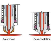
Figure 3: Valve gates for amorphous and semi-crystalline resin.
The gate area for amorphous resins should be thermally insulated from the nozzle and nozzle tip. Heat transfer from the nozzle to the gate area can delay solidification, leading to deformation in the gate area. In this configuration, the nozzle seal is located away from the molding surface where cooling lines can remove the heat transferred to the gate steel. The nozzle tip extends into the gate detail but does not directly contact the gate steel - further reducing possible heat transfer to the molding surface. This nozzle tip also can be used with semi-crystalline plastics that do not require high processing temperatures such as polypropylene.
A valve gate nozzle designed for semi-crystalline and high-temperature amorphous resins must conduct heat to the gate seal-off area to keep the resin molten. This is achieved with a nozzle tip that extends to the molding surface with an integral sealing surface. This nozzle tip configuration keeps the seal-off area at elevated temperatures. Cavity cooling lowers the external temperature of the tip - allowing the resins to freeze. This nozzle tip configuration usually results in a second witness mark where the nozzle tip is flush with the cavity steel.
Valve gates have been successfully used with abrasive resins containing fillers such as glass and carbon fiber. Care must be taken that wear-resistant materials are used for the valve stem and nozzle tip. A replaceable nozzle tip with an integral gate seal is the most appropriate choice for abrasive resins. The nozzle tip can be replaced at a lower cost than replacing a gate insert. Tapered valve gates also are recommended for abrasive applications. As described earlier, the quality of a cylindrical seal valve gate will degrade more rapidly than that of a tapered valve gate as wear affects the components.
Conclusion
Although higher in cost than thermal gates, valve gates offer tremendous value. In addition to the superior gate quality, valve gate nozzles can improve part quality and increase productivity. All of the benefits - not just gate quality alone - should be carefully considered when determining if a valve gate nozzle is best for your mold. In addition, valve gate applications should be reviewed with your hot runner supplier to ensure that the most appropriate nozzle style is used in your mold.
RELATED CONTENT
-
CAM Automation, Hot Runners, Asset Management & More: The Best of August
What does CAM automation, hot runners, and simulation software all have in common? They are all topics that made it into our top ten most-viewed content pieces in August.
-
VIDEO: Hot Runner Maintenance Tips
Scott Clark, Hot Runner Business Manager for Husky Technologies, breaks down maintenance practices for hot runner systems.
-
Hot Runner Truths, Myths and Overlooked Areas
Addressing hot runner benefits, improvements and everyday issues from the perspective of decades of experience with probably every brand on the market.