
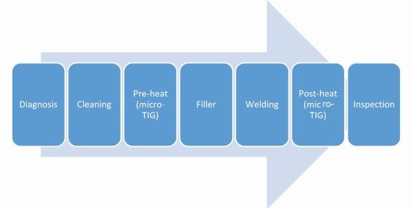
Under the Scope: Mold Repair Workflow
These seven steps can help any shop secure an effective mold repair procedure.
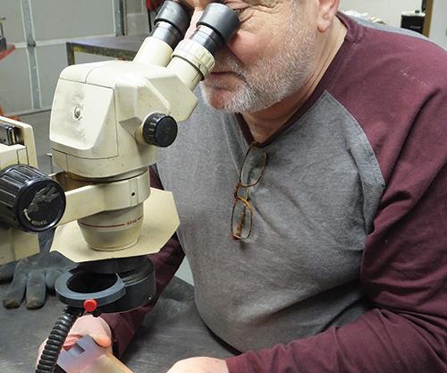
Examination through a microscope can help a welder diagnose the weld repair and understand the task at hand. Images courtesy of Toolweld Inc.
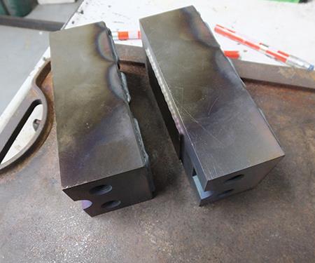
A color change to brown or purple in most steels indicates proper heating.


In most welding shops, there is a certain procedure for handling a mold from when it arrives for repair to when it is ready for a customer. At my company, it is a seven-step process that may require adjustments depending on whether we are using micro-TIG or laser welding. For example, preheating and postheating are often essential parts of micro-TIG welding, but not laser welding. Regardless of the process used, the following steps can help any shop secure an effective mold repair procedure.
Step 1: Diagnosis. Welders should ask a series of questions regarding the location of the weld, material type and the goal of the task in order to accurately diagnose the repair and devise the best welding solution. Communication between the welder and the engineer is critical. Any potential problems that might inhibit the welding process must be discussed. These problems include, for example, EDM recast layers, steel types, contamination, coatings and ease of access. In addition, the specific welding process to be used must be determined and discussed in terms of its advantages and disadvantages.
Step 2: Cleaning. Thoroughly clean all potential welding repair areas before welding begins to prevent contamination from causing porosity and microscopic cracks in the mold surface. Remove oil and grease with isopropyl alcohol, acetone or another special cleaning solution appropriate for use on molds. Dig out rust or pitting with a stainless steel brush. Its hard bristles can remove most contaminants. Do not use a stainless steel brush to clean a diamond-polished surface, however, as it will cause scratches. Also, if you are unable to completely remove contaminants in a difficult-to-reach area, explain to the customer before any welding takes place the problems that may occur in the weld.
Step 3: Preheating (micro-TIG). Depending on the size of the mold and the degree of damage, if it is made of steel and is to be micro-TIG welded, it should first be preheated. Preheating permits the use of lower amperage, which produces a smaller weld and helps reduce cracking. The preheating can take place on an electric hotplate, with a torch (for larger molds) or in a specialty oven. The preheat temperature parameters vary for each steel type, so follow the steel manufacturer’s guidelines. Typically, mold steels require a temperature range from 500°F to 700°F. A color change to brown or purple in most steels indicates proper heating. This is not true for 420 stainless steel, however, which will show no noticeable color change due to its high level of chromium. Chromium provides heat resistance and so requires the use of an infrared temperature gun or a temperature-indicating crayon to ensure the proper heating temperature is reached.
The microscopic heat-affected zone created by laser welding eliminates the need for preheating in those applications, although the material being laser-welded should be at least at room temperature. This reduces microscopic cracking in materials with a Rockwell hardness higher than 55.
Step 4: Filler choice. Check with your rod supplier to accurately match your filler rod to the steel to be welded, and be aware that the required diameter of filler rod may not always be available.
When selecting a filler rod, consider mold steel type, type of repair and expectations of the engineer/customer. For example, if the customer requires a weld with a lower Rockwell hardness for 420 stainless steel, use 420 or 410 stainless filler rod. The same applies with H-13 steel, in which case you should use H-13 or an H-13-modified filler rod (softer Rockwell hardness). Ultimately, the customer dictates the use of standard or modified filler rod, and the Rockwell hardness of a filler rod is a key factor. Generally, the lower hardness of softer filler rods provides crack resistance, and harder filler rods provide wear resistance and durability. A softer, modified filler rod may be used on repairs in inside corners, for example, because a hard filler rod can cause cracking in the center of the weld bead.
Step 5: Welding. Each welding process requires a specific technique, position and machine calibration. This is where welding experience and the machine manufacturer’s guidelines come into play. A seasoned welder knows how to accurately calibrate the starting micro-TIG amperage, laser beam power and displacement, and shielding gas displacement. He or she also knows that, with laser welding, positioning the laser beam to the correct distance and angle is critical to ensure the best penetration. Experience also shows that micro-TIG welding requires a special feeding technique when adding filler rods in diameters smaller than 0.015 inch, because rods of this size melt before entering the weld puddle. Lastly, an expert welder knows that preheated molds need to maintain the preheat temperature throughout the welding process to reduce the potential for cracking and improve the general weld-ability of the material.
Step 6: Postheating (micro-TIG). After welding, the mold should be postheated or stress-relieved, as this reduces hardness and other stresses in the heat-affected zone of the weld. Postheating is similar to preheating, except the temperature range is much higher (1,100°F to 1,250°F). It is important not to postheat the steel near the annealing point (1,350°F to 1,750°F), since this will lower steel hardness and cause changes in the dimension of the material. Using a tool to accurately test mold temperature during postheat is necessary. As with preheating, laser welding does not require postheating.
Step 7: Customer inspection. After postheating, the mold needs to cool down slowly to room temperature. Forced rapid cooling (using water or refrigeration) can shock the steel, causing cracks. Once the piece is cool enough to handle, clean it with isopropyl alcohol and a stainless steel brush, and return it to the customer. Upon delivery, the customer should inspect the weld
repair using a magnifying glass.
These seven steps serve as guidelines for a mold’s weld preparation and welding process. Exceptions can be made based on customer requests and parameters.


Related Content

Portable Low-Heat, Non-Arcing Resistance Welder for Mold Repair
Rocklin’s user-friendly MoldMender Micro Welder delivers simple and cost-effective localized repair in-house with precision and versatility, enhancing mold and die durability and reducing disassembly and downtime.
Read More
How to Maintain Heaters, Thermocouples, Valve Gates and Controls
An examination of real-world problems and solutions involving hot runner system maintenance.
Read More
5 Hot Runner Tips for Moldmakers and Molders
Best practices for initial hot runner tryouts and effective preventive maintenance.
Read More
Products and Services for Multiple Moldmaking Needs
New year, new technology roundup! Featured here is a collection of product offerings, from profile milling cutters to industry-specific CAD/CAM software to innovative hot work tool steels.
Read MoreRead Next

Under the Scope: Considerations for Mold Repair Welding
This new series is intended to arm toolmakers and engineers with the necessary knowledge to make better informed decisions during tool repairs, including an understanding of welding terminology, procedures and challenges.
Read More
How to Use Strategic Planning Tools, Data to Manage the Human Side of Business
Q&A with Marion Wells, MMT EAB member and founder of Human Asset Management.
Read More
Reasons to Use Fiber Lasers for Mold Cleaning
Fiber lasers offer a simplicity, speed, control and portability, minimizing mold cleaning risks.
Read More