
The Secrets to Hard Milling Success
The Secrets to Hard Milling Success


Throughout the last few years, hard milling has captured the attention of manufacturers around the world. These manufacturers are typically focused on the mold and die industry where materials such as P20, H13, S7 and others are commonly cut. Traditionally, core and cavities from these materials are manufactured in the hardened state using EDM. Through the years, new technologies have been developed where these materials can be, in most cases, machined directly into hardened material using new toolpath processing techniques in combination with high-speed machining (HSM) techniques to form hard milling. These materials can range from 45 HRc to as hard as 64 HRc.
Components of Hard Milling
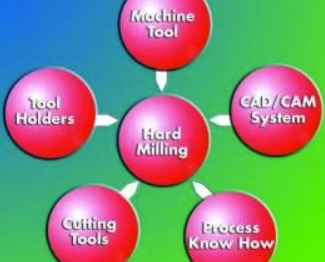
Figure 1: Circle of Technology
Hard milling uses a combination of several key technologies that can be categorized into components. These components are defined as the machine tool, the CAD/CAM system, the tool-holders, the cutting tools and the know-how. To be successful at hard milling, these components must come together in what can be called The Circle of Technology as illustrated in Figure 1. Each component will be examined within the circle so that a clear understanding can be developed to facilitate successful hard milling of small- to medium- sized parts.


Machine Tool
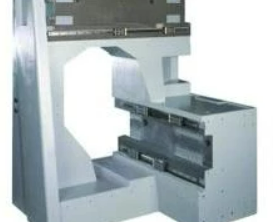
Figure 2: Polymer concrete machine base
Although all of the components of the circle are important, the machine tool component is, by far, the most significant. The machine must be designed for hard milling and have some of the same characteristics found in a HSM center. The base construction and the individual components of the machine such as the drive train, the spindle and the CNC control, etc., must be capable of handling all the demands of hard milling. The base construction of the machine must be extremely rigid and have a high degree of damping abilities. These characteristics are commonly found in machines constructed from polymer concrete (see Figure 2).
Machines constructed from polymer concrete typically have six to ten times the damping characteristics over machines constructed from cast iron. Polymer concrete also has excellent mechanical and thermal characteristics. The drive train should consist of digital drive technology for optimum acceleration and deacceleration. This technology provides the CNC control with the ability to perform a high degree of contouring accuracy encompassed with excellent dynamics capabilities. These characteristics will help minimize cutting tool wear.
Spindle
Another important aspect of the machine is its spindle. The spindle should be a vector-controlled motorized spindle. Vector-controlled spindles provide a great deal of flexibility, offering high torque at low rpms and maximum power for large speed range. The HSK interface between the tool holder and spindle should be used. This will provide minimal runout and excellent balancing at high speeds. Hybrid-ceramic bearing in the construction of the spindle will offer some excellent benefits including increased spindle stiffness, accuracy and temperature stability.
CNC Control
The performance of the CNC control is critical. A control with maximum block processing rate will ensure that the received data will be handled quickly and efficiently. This data should reside on a hard-drive located on the control. Incorporating numerical algorithm to calculate the velocity profile in the control will assist in smoothing machine motion. Additionally, all servo systems on a CNC machine exhibit a characteristic called servo lag. Servo lag is the actual amount that the machine position trails the position commanded by the control. In hard milling, any motion that is not continuous with the programmed path will create excessive stresses on the tool, causing the possibility of premature failure. Therefore, it is essential that the control have the ability to handle and control servo lag.
Toolholders
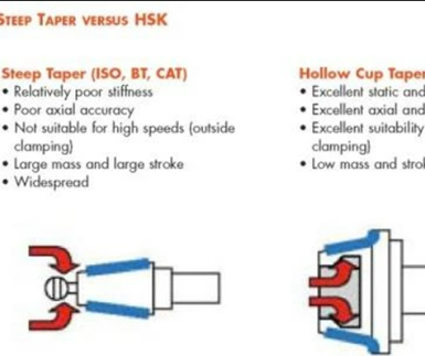
Figure 3: Steep taper versus HSK.
Continuing within the circle, tool-holders play an important role in hard milling. Because hard milling requires a large range of rpms-from low rpms for a roughing application to high rpm for HSM-only the HSK interface between the toolholder and spindle interface should be used. This will provide a very rigid and balanced tooling setup over the ISO taper interface. The advantages of HSK over taper tooling are illustrated in Figure 3.
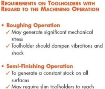
Figure 4: Requirements on toolholders.
The cutting tool can be held by several methods. These methods include collet chuck, hydraulic expansion, shrinkfit and power shrinking. The method selected should be determined by the requirements of the machining operation (see Figure 4).
Collet chucks are by far the most flexible. In addition to offering maximum flexibility, they are easy to handle, provide excellent shock absorbing characteristics and offer an excellent range of clamping diameters. These are suitable for aggressive roughing and semifinishing of hardened materials.
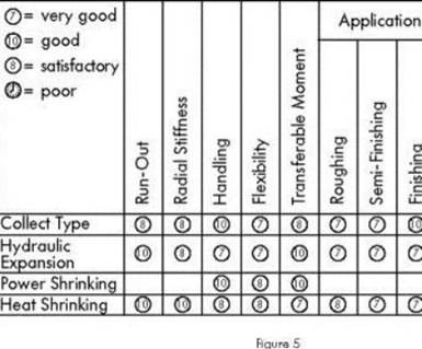
Figure 5: Comparison of holding systems.
Hydraulic expansion toolholders also provide ease of use as well as high clamping forces and minimal runout, which will provide extended cutting tool life. However, hydraulic tooling can be expensive and bulky to use. Similar to collect chucks, hydraulic tooling is an excellent choice for roughing and semifinishing operations. For finishing those hardened cavities and cores with a high degree of accuracy and quality, power and heat-shrink toolholders provide excellent characteristics. Figure 5 outlines the pros and cons between all four systems. Today, all systems are commonly available from most tooling suppliers.
Cutting Tools
Although hard milling uses many aspects of HSM, the selection of appropriate cutting tools is most important in hard milling. Furthermore, cutting tools are a significant cost factor in both hard milling and HSM; making a good choice can help save money. One of the main contributing factors of hard milling failure is the cutting tool. Many companies tend to skimp on selecting high-quality cutting tools, opting for less than adequate tools. To ensure that quality tools are selected, it is best to select an OEM who specializes in tools for hard milling or offers a well-defined product line for hard milling. The OEM should have technical staff on hand to assist in selecting the appropriate cutting tool for a particular hardened material and cutting strategy.
For roughing hardened materials, four-flute end mills or higher are recommended. This will provide small chip loads while having the ability to cut at higher feedrates. Additionally, torus end mills are recommended for roughing because the sharp edges of conventional end mills are not sufficiently resistant against the possibilities of vibration and thermal stress when cutting hardened materials.
The selection of cutting tools should be short with short flute lengths along with a helix angle of approximately thirty degrees. A thirty-degree helix has proven to be optimal for chip flow and dispersal of heat. The parent carbide substrate should also be considered. Only fine or ultrafine grain sintered carbides should be used. Sintered hard carbide is a composite material based on powder metallurgy. A binder (usually cobalt) is used to bond carbide particles. Tungsten-, titanium-, tantal- or niobcarbide are the most used elements and provide the required hardness at high temperatures and wear resistance. With a reduction of the grain size of the carbide particles to about 0.5 to 0.6fm, the edge strength can be further increased, while the tendency to adhesion can be reduced. For larger hardened cavities and cores, a selection of inserted cutting tools should be considered. Carbide inserts are less expensive than end mills and by rotating the insert, insert life can be extended. However, these tools are not typically designed for high spindle speeds and runout can be significant. There is also a significant safety risk if improper handling occurs.
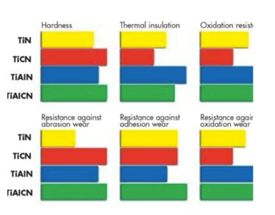
Figure 6: Comparison of cutter tool coatings.
Hard milling creates a great amount of stress on the tool from high heat and abrasive wear. To help overcome these stresses, coatings must be applied to the cutting tool. These coatings offer a protective layer on the tool, substantially increasing its life. The most common coatings are titanium nitride (TiN), titanium carbon nitride (TiCN), titanium aluminum nitride (TiAlN) and titanium aluminum carbon nitride (TiAlCN); each coating has its benefits (see Figure 6). Coating selection should be made based on individual properties and the OEM may dictate these when selecting a cutting tool. Figure 7 highlights the more important properties related to the coatings.
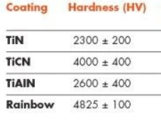
Figure 7: Comparison of coatings properties.
The titanium-based hard material layers such as TiCN and TiAlN are the most commonly used protection layers for HSM and hard milling cutting tools. The resistance to wear (hardness) is the most important property of TiCN, while TiAlN has a better heat and oxidation resistance property. The OEM may also further enhance the coatings by offering unique blends, perhaps creating a leading edge over coating quality and tool life. Recently, other advances in coatings have entered the market such as proprietary coatings. Commonly called Rainbow coating, it is a proprietary multielement PVD (physical vapor deposit) coating offering a competitive edge over traditional nonpropriety coatings.
Flood coolants are traditionally used throughout the machining process to help disperse heat and remove chips from the work area and the cutting tool. Hard milling often generates a tremendous amount of heat over conventional machining. This heat transferred into the chip and the use of flood coolant during hard milling causes the coolant to vaporize as it hits the hot chips. The use of coolants also can create thermal instability with the tool. Therefore, flood coolants are not commonly used in hard milling. To help displace chips during the cutting process, compressed air is used. Additionally, a combination of oil/mist is often selected. The addition of oil helps reduce friction, therefore increasing tool life and surface finish. When using oil/mist, an oil/mist extraction unit should be integrated into the machine tool to help remove the oil from the air.
CAD/CAM
Falling in line, the CAD/CAM system is another equally important component. Today's CAD/CAM systems have greatly advanced over the years, providing a wide variety of system tools and capabilities. Furthermore, development continues to grow at an outstanding pace. However, not all of today's systems are created equal and it is important to realize that there are still many systems that do not have the built-in tools or strategies to create toolpaths for hard milling or HSM.
Although no system is devoted entirely to hard milling, many that offer HSM capabilities will have the same strategies for hard milling since there is a common relationship between the two technologies. When considering hard milling, strategies that keep the tool in motion should be used for hard milling. This will ensure that the tool is continuously cutting with a constant chip load. This is one of the more desirable conditions to maintain for hard milling. Before further discussion on machining strategies can begin, a careful review of the CAD model is important.
One of the common problems associated with CAD/CAM programming is the model. Many companies import data from other systems using a variety of importing tools. In particular, job shops may deal with various clients, who are using a variety of different CAD systems. In this case, a file transfer format needs to be defined to transfer geometry data from the client CAD system to the CAM system. In order to avoid time-consuming repairs of the model, it is very important to select the proper file format for a data transfer. Some CAM systems offer special interface options to directly read in file formats from other CAM systems. When data is imported, problems can pop up. These problems range from missing trimmed surfaces to bad solid models causing numerous headaches for creating efficient toolpaths. These problems need to be fixed before developing toolpaths.
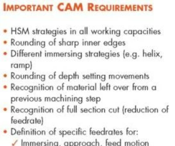
Figure 8: CAM system requirements
Poorly developed models also are a common problem. Typically, how a model is created is going to dictate what machining techniques are used. If machining strategies are not considered during the development of the model, then the programmer may not be able to use certain toolpath strategies. Without these considerations, hard milling a cavity or core may not always be suitable without modifying the model. Some of the important requirements of the CAM system are shown in Figure 8.
Before toolpaths can be applied, there must be a complete analysis of the part. Not all parts are suitable for hard milling. The specific areas to be machined should be clearly identified, determining the smallest internal radius and largest working depth. A 4:1 ratio of length to tool diameter commonly does not pose any problems. Problems arise when the ratio grows, and careful consideration should be made towards the feasibility of success. When ratios are excessive, experience at hard milling will have an important role in determining how successful one will be. Hard milling with tool diameters as small as 0.005" can be accomplished as long as care is taken to maintain a constant chip load and machining at minimal cutting depths. These depths can commonly range from 0.0002" to 0.0005" on such small tools. Toolpath strategies can now be determined.
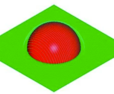
Figure 9: Single parallel finishing toolpath strategy.
As mentioned earlier, in hard milling it is important to keep the tool in motion avoiding dramatic changes in direction. Therefore, depending on the complexity of the part, multiple toolpath strategies may be required to complete the part. The process of recognizing and separating key areas of the part and applying different toolpath strategies is commonly called modular toolpath programming (MTP). This method of programming is generally used in HSM to maintain high cutting speeds. Similarly, MTP can be used to help keep the tool in motion while avoiding dramatic changes in direction. In its simplest form, Figure 9 illustrates a single parallel finishing toolpath strategy. Although simple, this is not the ideal method for machining this part in its hardened state. If individual part features are recognized and separated, two different strategies can be applied to this part
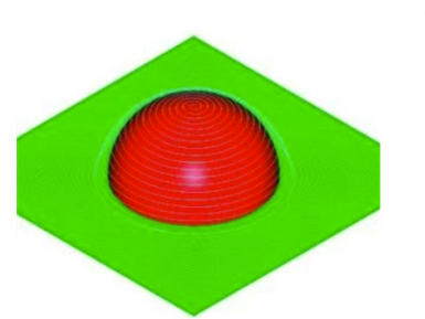
Figure 10: Two part strategies
(see Figure 10). In this simple example, a spiral morph toolpath on the green surface, combined with a true spiral from top to bottom on the red surface, provides a suitable method for machining this part. Toolpath quality is commonly overlooked in a CAM system. Figure 11 represents what appears to be a normal looking toolpath; but upon further evaluation, it is revealed that there are many unnecessary changes in the toolpath direction (see Figure 12).
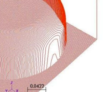
Figure 11: Apparent normal-looking toolpath.
Stepping back to our machine tool, builders have incorporated elaborate acceleration and deceleration servo tuning algorithms as well as complex servo lag algorithms (look ahead features) into their controls to enhance motion control. These look ahead or control feedrates by analyzing directional changes within the NC code. The greater the directional change (for example, zero to ninety degrees) the more the control has to slow down to maintain the programmed path. In hard milling, these abrupt changes in toolpath direction create dwells and slow downs, which can have an effect on tool life and surface finish (see Figure 12). Therefore, toolpath quality should be an important feature of your CAM system.
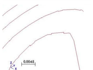
Figure 12: Toolpath changes.
Programming errors have a tendency to be less forgiving when conventional machining techniques and softer materials are used. With hard milling and HSM, programming error will no doubt have severe consequences if not caught in time. Cutting tools can easily be broken; tool holders, fixtures and even the machine can be damaged costing hundreds to thousands of dollars. Personal safety also can be at risk. To ensure programming errors are caught before they happen, the CNC code should be thoroughly reviewed for errors. Most CAD/CAM systems incorporate some type of toolpath verification or toolpath simulation within their software. Unfortunately, many of them only view the intermediate file rather than the posted NC code or the C/L toolpath file where errors can occur. Therefore, care should be taken to ensure that the posted NC code is reviewed for errors. If your CAD/CAM system does not have the tools to view or simulate the NC code directly, there are numerous software packages on the market that will. These products can range from a few hundreds dollars to several thousands of dollars but they will save you many major problems by eliminating potential crashes and safety issues at the machine.
Know-how
Finally, proper know-how and training are vital keys to being successful at hard milling. You can have all of the above elements but they are no good to you without a clear understanding of principle processing procedures. Often, an entirely new approach is required to gain the profitable advantages of the hard milling process over conventional milling. The successful employment of the hard milling process is based on specific know-how, advanced knowledge of the basics of the HSM process, choice of appropriate cutting tools, choice of appropriate clamping systems for cutting tools (and parts) and professionalism, using an HSM capable CAD/CAM system.
There are many resources for hard milling. The supplier or OEM should be your first choice. For example, a cutting tool representative will be able to assist in selecting the correct feeds and speeds for a particular cutting material. Many work directly with machine tool builders for adequate testing of their tools. Manufacturers of tool holders commonly work with builders to share and gather information regarding equipment performance. This also holds true for CAD/CAM developers who commonly work closely with machine tool builders testing new machining strategies and sharing ideas on new and improve machining methods. Training must be on a continuous basis.
With a clear understanding of all the components in this Circle of Technology, one will have a better awareness of the tools needed to be successful at hard milling.


Related Content

Customized CAM Strategies Improve Five-Axis Blow Mold Machining
The proper machining process and workflow can impact blow mold production, making your CAM software selection critical.
Read More
Ten Things You Need to Know about Circle Segment Milling
Considerations for evaluating if circle segment end mills or conical barrel cutters are right for your mold machining applications.
Read More
Machining Center Spindles: What You Need to Know
Why and how to research spindle technology before purchasing a machining center.
Read More
Developments in High-Speed Machining Technology
There have been many exciting developments in high-speed machining relative to machining centers and controls, tooling and CAD/CAM systems.
Read MoreRead Next

CAM for Hard Milling
A brief overview of some of the CAM requirements, challenges and strategies for successful hard milling.
Read More
Reasons to Use Fiber Lasers for Mold Cleaning
Fiber lasers offer a simplicity, speed, control and portability, minimizing mold cleaning risks.
Read More
How to Use Strategic Planning Tools, Data to Manage the Human Side of Business
Q&A with Marion Wells, MMT EAB member and founder of Human Asset Management.
Read More