
Success with Conformal Cooling Using Direct Metal Laser Sintering
Featured project from Phillips Plastics. The design for the DMLS conformal cooling tool insert incorporated channels that were designed to quickly and evenly cool individual cavities within the piece, which would not have been possible with conventional mold technologies. Expectations were reduced cycle time and higher quality parts.
DMLS reopens the door for tool designers and moldmakers to effectively design high-performance, high-efficiency conformal cooling tools.
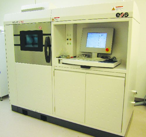
EOSINT M270 DMLS machine.
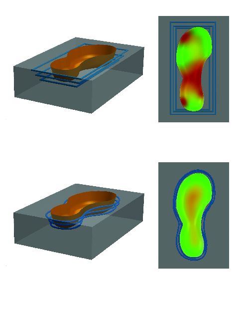
(top) Traditional cooling lines; (bottom) conformal cooling lines.
Simulation software helps find the right layout in critical cases.
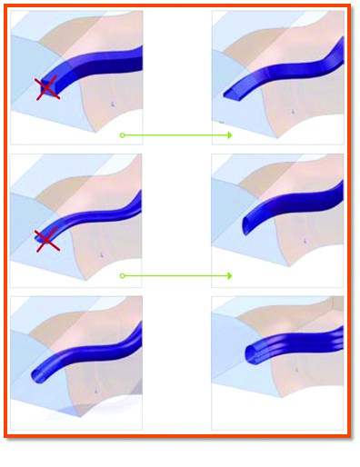
In addition to circular cooling channels, designers can use more complex shapes in order to reach greater cooling performance.
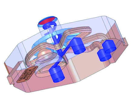
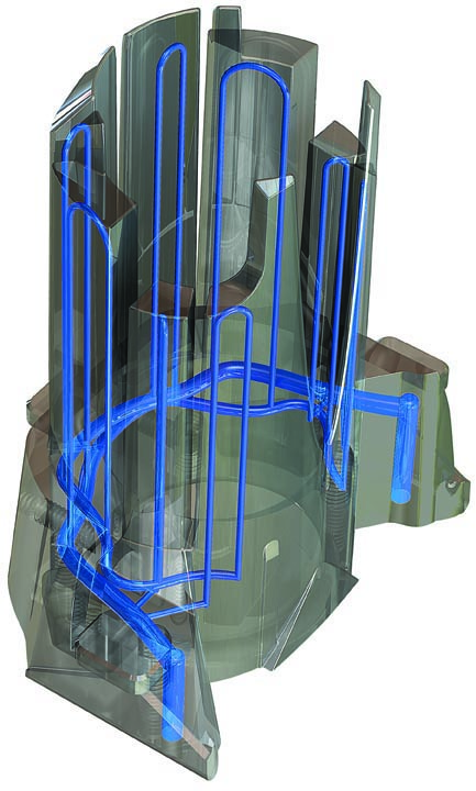
Design of tool insert showing conformal cooling channels.
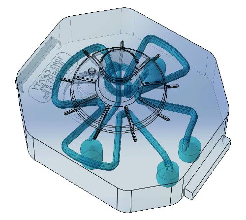
Design and 3D CAD configuration before start of build.
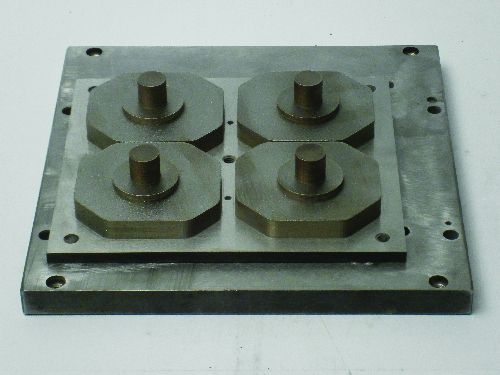
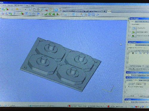
Completed build of tool inserts on build plate.
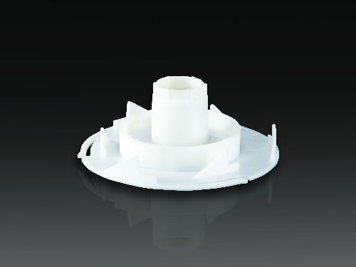
Finished shot from four-cavity DMLS conformal cooing tool.
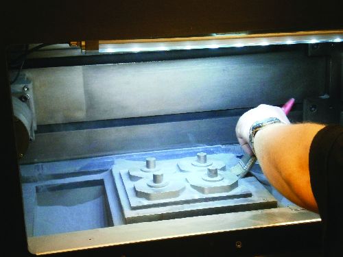
Cleaning off extra powder from finished build in DMLS machine.


Conformal cooling in tool design is a concept that’s fundamentally sound. The trouble lies in the mechanics. Design obstacles imposed by performance boundaries in available machining processes often put its merits out of practical reach. The emergence and attainability of DMLS technology gives toolmakers, like those at Phillips Plastics, the design latitude to make conformal cooling a profitable reality.
Conformal cooling is the holy grail of injection mold temperature systems. It’s the most effective means for maximizing tool performance. But, implementation has been historically problematic with straight line methods or time/cost consuming secondary operations. DMLS gives the current state of conformal cooling a technological upgrade that can create tools and inserts with precisely placed and seamless channels (see Figure 1).


The featured project is from Phillips Plastics. The design for the DMLS conformal cooling tool insert incorporated channels that were designed to quickly and evenly cool individual cavities within the piece, which would not have been possible with conventional mold technologies. Expectations were reduced cycle time and higher quality parts.
Defining DMLS
Direct Metal Laser Sintering (DMLS), developed by EOS GmbH, is an additive metal technology that builds directly from 3D CAD files. The technology takes a CAD file and slices the object into thin 20 micron (.0007”) or 40 micron (.0015”) layers. The machine then uses those layers to build the part using a 200 watt fiber optic laser. This locally melts each metal powder layer onto the previous layer, eliminating the need for a binder. The result is a fully dense metal part.
Technical Data
The M270 machine (see Figure 2) has a build envelope size of 9.5” x 9.5” x 7.5”. On the updated M280 machine, there is an increased build envelope size of 9.5” x 9.5” x 12”. It’s possible to orient diagonally to build certain good candidate parts that are longer than the machine’s base dimensions. Another option is to build in segments and weld parts together.
Typical tolerances as built in DMLS are 0.005” on the first inch and an additional 0.002” each inch thereafter, but with some fine-tuning—respective to individual projects—the machines are capable of tighter tolerances.
DMLS Materials
DMLS Materials are made from wrought metal that’s been water or gas atomized into a fine powder. They are almost identical to current alloys on the market. Most DMLS materials meet or exceed ASTM standards: DM20 Bronze Alloy; PH1 Stainless Steel 15-5 (meets materials specification ASTM A564-04 (XM12), ASTM A693-06 (XM12); GP1 Stainless Steel 17-4 (fulfills the requirements of AMS 5643); MP1 Cobalt Chrome alloy (conforms to the composition UNS R31538); MS1 Maraging Steel (conforms to US classification 18% Ni Maraging 300); AlSi10Mg Aluminum; Nickel Alloy IN718 (composition corresponding to UNS N07718, AMS 5662, AMS 5664, W.Nr 2.4668 and DIN NiCr19Fe19NbMo3); and, Ti64 Titanium Ti64 (fulfills the requirements of ASTM F1472).
Secondary Processes
The inherent design freedom of DMLS often reduces the need for secondary processes. For example, text may be incorporated in a CAD file to build an engraved part. However, when desired or needed, parts built on a DMLS machine are secondary process-friendly (see Figure 3). The options include machining, tapping, welding, coating, plating and/or texturing, EDM and engraving.
Polishing requires some pre-build planning. DMLS parts can be polished to a mirror finish, but the size of the part must be altered in the CAD file (.008” up to .030” depending on desired finish) to account for material removed during the polishing process.
The Channels
An effective temperature control system saves time and costs in the process of injection molding. Conventional cooling relies on things such as the conductivity of the mold material and straight line drilled channels. Its focus is mold cooling. Costly inserts made with alloys that have higher conductive properties aid the process. Conformal cooling uses strategic channels concentrated around the product. Its focus is on cooling the injected melt.
When plastic melt cools evenly, internal stress is minimized. This results in a higher quality part with little to no warping or sink marks. An added bonus comes in the form of drastically diminished scrap rates. Productivity gained in upgrading from a conventional tool to a tool with conformal cooling channels can be upwards of 30 to 60 percent (see Figure 4). Properly maintained mold temperature also tends to improve tool life and the high costs associated with replacement tools.
CNC machining for conformal cooling is disadvantaged by straight line drilling. The intersecting channels, complex coolant routing and zero velocity areas are difficult to manage and the process can’t achieve a controlled or uniform distance from the melt. Secondary sinker EDM to complement CNC tooling can prove costly, both in time and money.
DMLS builds conformal cooling channels into the tool as part of the tool. Channel geometries around the cavity can be fluid and controlled for optimal cooling.
Even combined systems with separated cooling and heating channels are possible or the split between main systems (for the control of the global temperature) and specific systems (for the handling of close-to-cavity critical temperatures) can be performed with DMLS. This opens up potential for future applications. Turnaround times for DMLS can be as short as five to seven days.
Guidelines
The recommended material for tooling is MS1 Maraging Steel. It is the hardest, most durable material and is used in 95 percent of all DMLS tooling. It can be post-hardened to 54 Rockwell and withstand temperatures up to 750°F before yielding.
In cases where a tool insert created with DMLS needs to be polished, it’s best to have it done by a professional mold polisher to ensure tight tolerances.
DMLS can build channels down to 1mm diameter; however, channels this fine can only be put into service with specially treated fluids to avoid clogging. Simulation software helps find the right layout in such critical cases (see Figure 5).
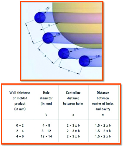
According to experience, the optimal diameter should be chosen between 4-12 mm (depending on the design of the product). These values are preferred values to be used in ideal cases, as in practice sometimes tool inserts are too slim to make it possible to exactly follow this rule (for example, a closely placed pair of ejector pins, thin walls etc.). In cases of complex geometrical conditions it can be necessary to design much smaller diameters—for example when eliminating a hot spot.
In addition to circular cooling channels, designers can use more complex shapes in order to reach greater cooling performance. The feasibility criterion supposes a cross section, which is self supporting. This means the angle of overhanging areas should be above 40° to horizontal. On the last picture of Figure 6 the cooling performance can be increased due to the ribbed shape and the higher expected turbulence in the channel (higher Reynolds number). This is the channel Phillips chose for the featured project. Some overhanging angles require support during the build process. Supports cannot be removed in channels. Your DMLS operator should be able to help identify suspect angles prior to building.
Case Study: Phillips Plastics
Phillips Plastics came to us with a design for an insert that was to be part of a four-cavity mold to replace the one-cavity conventional mold currently in operation (see Figures 7 and 8).
GPI Prototype used an H13 tool steel plate and built DMLS tool inserts with conformal cooling channels incorporated onto the plate (see Figures 9 and 10). We sent the plate with the completed build to Philips Plastics for them to post machine and wire cut the inserts off.
Phillips Plastics confirmed conformal cooling using DMLS allowed for a shorter cycle time. It also produced a higher quality part (flatness and dimensionally correct; Figure 11).
Tonnage: 80 ton Netstal
Amount of Material: .0774 pounds per shot
Type of Materia: Celanex 2401MT
Cycle time with 1-cavity conventional tooling: 16.78 seconds
Cycle time with 4-cavity DMLS conformal cooling: 13.02 seconds
CAVITY-TO-CAVITY CYCLE TIME IMPROVEMENT: 22.4%
Flatness spec with conventional tooling: .25 mm: .15 min .223 max
Flatness spec with DMLS conformal cooling: .2 mm: .080 min .161 max
QUANTIFIABLE PART FEATURE IMPROVEMENT: 20%
"The people at GPI were very helpful and easy to work with,” says Wayne Nielsen from Phillips Plastics Corp.
Summary
Conformal cooling in many applications was considered a lost cause due to the problems faced in execution. DMLS reopens the door for tool designers and moldmakers to effectively design high-performance, high-efficiency conformal cooling tools. DMLS technology has consistently proven to create tools that categorically improve productivity. The drawbacks are size limitations imposed by the build envelope and gaps in designer/operator communication. The results and returns seen by Phillips Plastics in this case study are evidence of the practicality in conformal cooling using DMLS.
References
Mayer, Siegfried. Optimised Mould Temperature Control Procedure Using DMLS. Tech. 2008.
Shellabear, Mike & Weihammer, Joseph: Tooling Applications with EOSINT M. In: EOS Whitepaper, Krailling – September 2007.
Nielsen, Wayne: Mold Manufacturing Manager Phillips Plastics Corp.


Related Content

Fundamentals of Designing the Optimal Cooling System
The right mold components can help improve mold cooling and thereby produce higher-quality parts.
Read More
Hands-on Workshop Teaches Mold Maintenance Process
Intensive workshop teaches the process of mold maintenance to help put an end to the firefighting culture of many toolrooms.
Read More
Solving Mold Alignment Problems with the Right Alignment Lock
Correct alignment lock selection can reduce maintenance costs and molding downtime, as well as increase part quality over the mold’s entire life.
Read More
Laser Welding Versus Micro Welding
The latest battle in finely detailed restoration/repair of mold materials.
Read MoreRead Next

Reasons to Use Fiber Lasers for Mold Cleaning
Fiber lasers offer a simplicity, speed, control and portability, minimizing mold cleaning risks.
Read More
How to Use Continuing Education to Remain Competitive in Moldmaking
Continued training helps moldmakers make tooling decisions and properly use the latest cutting tool to efficiently machine high-quality molds.
Read More
How to Use Strategic Planning Tools, Data to Manage the Human Side of Business
Q&A with Marion Wells, MMT EAB member and founder of Human Asset Management.
Read More