
Simulate Your Way to a Better Mold
How incorporating simulation of the cooling stage of the injection molding process can help mold designers and molders make their tool as efficient as possible.
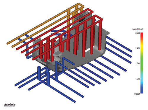
Figure 1. Simulation can help determine the flow rate required to achieve turbulent flow and minimize temperature rise.
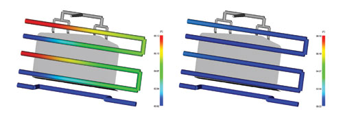
Figure 2. Ensuring turbulent flow minimizes the coolant temperature rise through the circuit.
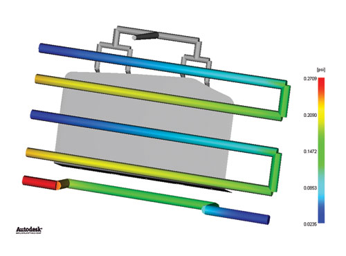
Figure 3. Pressure drop throughout the circuit should be considered when designing the cooling layout.
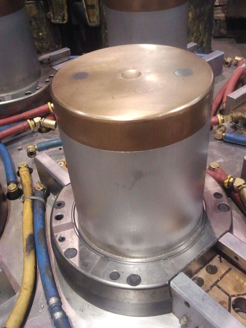
Figure 4. Image of mold with beryllium copper core cap.
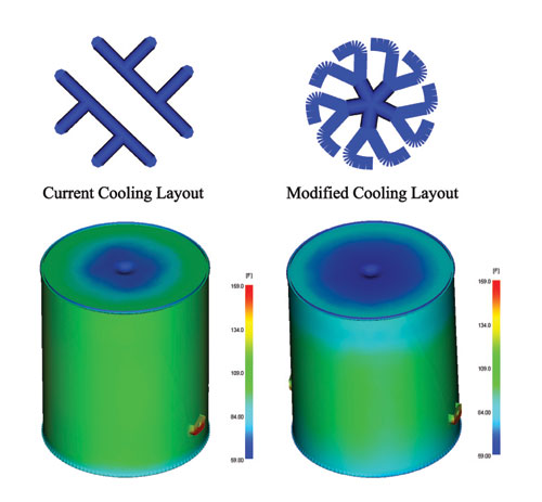
Figure 5. By modifying the current cooling layout the mold temperature within the core was reduced.
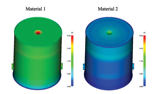
Figure 6. The predicted cycle time was reduced by changing the material.


The use of simulation software has become a ubiquitous tool for injection molded plastic parts and mold design. When used early in the design stage, simulation can provide designers and engineers with useful insight on part performance and how to manufacture plastic parts. According to Brian Wagner, Engineering Manager at Carlson Tool and Manufacturing, “The use of simulation allows our company to predict shrinkage, suggest product or mold changes to control warp, and verify that we have sufficient and balanced cooling to meet or beat the targeted cycle time. It also allows us to ensure that the mold will function to the customers’ expectation upon delivery.”
However, the rise of the ever-expanding global economy demands more than just manufacturing acceptable parts. The new world standard is quality parts, faster. Moldmakers and molders are constantly asked to cut seconds off the cycle time. Although this is a common demand it can be a daunting task that makes it difficult to know where to start. Through the use of commercial mold filling packages engineers can determine how to optimize the process and if it can be improved.


Examining the injection molding process reveals that the majority of the cycle time is dedicated to cooling the part. Often accounting for two-thirds of overall cycle time, the cooling stage of the process is the most beneficial stage to optimize and improve to reduce cycle time. Yet often the cooling layout is one of the last aspects of the mold design to be addressed. By optimizing the mold design and cooling layout you can improve your productivity and your bottom line. So what information can be derived from a cooling analysis?
Optimized Coolant Conditions
An injection mold is essentially a heat exchanger. The molten plastic introduces heat into the mold and the coolant extracts the heat out of the mold. Most mold designers will concentrate cooling circuits in high heat load areas, and reduce the number of circuits in low heat load areas. Once the initial mold design and cooling layout have been established it is important to maximize the heat transfer between the part and the mold. With all other parameters fixed the most important factor in determining how much heat can be extracted by the coolant is the flow rate through the cooling channels. Simulation software can allow the user to determine the required flow rate through the cooling channels (Figure 1), the temperature of the coolant in the cooling circuit (Figure 2) and the pressure required to maintain that flow rate (Figure 3).
Flow rate: The important word when determining the flow rate required to maximize heat transfer in a mold is turbulent. Ensuring turbulent flow maximizes the heat transfer between the mold and the coolant and helps maintain a more uniform coolant temperature from inlet to outlet. Engineers use a dimensionless number called Reynolds number to help them determine when the flow has transitioned from the laminar regime to the turbulent regime. The Reynolds number is directly proportional to the flow rate and density of the coolant, and is inversely proportional to the viscosity of the coolant. This transition occurs when the Reynolds number is greater than 5,000. If the coolant used and the diameter of the cooling channel are fixed the only way to increase the Reynolds number and ensure turbulent flow is to increase the flow rate.
Temperature: In addition to maximizing the heat transfer between the coolant and the mold, ensuring turbulent flow can also help maintain a more uniform coolant temperature through the cooling circuit. General guidelines suggest that the coolant temperature should not rise more than 5F while in the circuit. Minimizing the temperature rise allows the cooling rates throughout the circuit to remain more uniform, which helps maintain a more uniform mold temperature. Figure 2 shows that if we have a flow rate that creates a laminar flow (i.e. Reynolds number less than 5,000), the coolant temperature increases about 8F. However, if we increase the flow rate so the flow is turbulent, the temperature rise is less than 2F.
Pressure: So what is restricting a molder from simply pushing as much coolant through a mold as possible? The answer is pressure. As the flow rate increases, for a cooling circuit the pressure required to maintain that flow rate also increases, and this requires greater pumping power. Additionally, the longer the cooling circuit and the more restrictions (i.e. change in flow direction and use of quick connects), the more power that is required to maintain that flow. Once the flow has become turbulent, increasing the flow rate further provides diminishing returns in heat extraction while increasing the pumping power substantially. This extra energy consumption can reduce profit margins, while providing minimal benefit. Therefore, these three variables should be considered collectively when designing the cooling layout.
Effectiveness of High Conductivity Inserts
A common method of reducing cycle times is incorporating high conductivity inserts into the mold design. Materials such as beryllium copper or aluminum have thermal conductivities that are much higher than that of traditional tool steels. The use of these higher conductivity materials can allow for the mold surface temperature to remain lower and faster heat extraction from the part, if used properly. However, just having cooling channels run through the high conductivity inserts is not always enough to help reduce the temperature of the mold. Additionally, the price of these materials can be significantly higher and a balance between cost and cooling efficiency must be achieved.
Figure 4 shows a can that incorporates a beryllium copper cap on the core of the mold. By incorporating the higher conductivity cap it was anticipated that a cooler mold temperature could be maintained on the core side of the tool, which would help reduce the cycle time. An initial cooling analysis showed that with the current cooling layout the temperature would be reduced, but was not sufficiently reduced to justify the added cost of the cap. Therefore, the cooling circuit layout was modified within the cap to help maintain the lower mold temperature (see Figure 5). By increasing the surface area between the coolant and the high conductivity insert the mold temperature dropped by 20F. This analysis quickly showed the moldmaker an issue with the proposed cooling layout and an acceptable solution was found that allowed the moldmaker to save machining time and the cost of reworking the material.
Cycle Time Limitations
Another benefit to simulating the cooling stage is to understand what is happening inside the mold. When asked to reduce the cycle time, it is difficult to determine where energy should be focused, since the limiting factor is rarely known. Is it the material, is it the geometry or is it the cooling layout? Using the results of the simulation one can determine what is limiting the cycle time.
Even with an optimized cooling layout and mold construction, the geometry and material of the part may not allow for the desired cycle time to be achieved. From basic injection molding theory we know that the cycle time is directly proportional to the square of the part thickness and is inversely proportional to the thermal diffusivity of the resin. This means that if the wall thickness of the part is doubled, the expected cycle time would be four times longer. This also means that the polymer chosen can influence the cycle time. While cycle time is not a high priority when deciding what material is best for the application, there are often several resins that meet the performance requirements. The addition of additives such as talc, glass fibers,or carbon fiber can influence thermal properties of the base resin and allow the resin to cool faster. Awareness of the thermal behavior of the different resins could mean the difference between meeting the quoted cycle time or not.
Returning to the can example presented earlier, the moldmaker was able to reduce the cycle time by incorporating the beryllium copper cap and modifying the cooling layout. However, the end customer still wanted to further reduce the cycle time. After running several additional iterations it became clear that the combination of the can geometry and the material selected would not allow further reduction for the cycle time. The geometry could not be modified due to performance requirements, so an alternative resin (Material 2) was simulated to see its effect on the cycle time. Figure 6 shows that changing the resin allowed the cycle time to be reduced to meet the desired cycle time.
Summary
As pricing pressures continue to force our industry to find further innovative ways to manufacture parts more economically without sacrificing performance, it becomes our responsibility to determine the viability of these demands and to find solutions. The use of simulation has been a long-standing tool to injection molders and toolmakers to determine how to optimize the fill and pack stages. However, analysis of the cooling stage has often been overlooked. Simulating the entire injection molding process provides insight into where energy should be focused to help our customers bring their product to market faster while improving the bottom line.
For More Information:
The Madison Group
(608) 231-1907
erik@madisongroup.com
www.madisongroup.com


Related Content

Products and Services for Multiple Moldmaking Needs
New year, new technology roundup! Featured here is a collection of product offerings, from profile milling cutters to industry-specific CAD/CAM software to innovative hot work tool steels.
Read More
OEE Monitoring System Addresses Root Cause of Machine Downtime
Unique sensor and patent-pending algorithm of the Amper machine analytics system measures current draw to quickly and inexpensively inform manufacturers which machines are down and why.
Read More
Mold Innovations Power Unique Auto Lighting Elements on Hummer EVs
Diamond machining, electroforming of micro-optical inserts and modified latch-lock system help injection molds produce unique forward lighting elements.
Read More
The In's and Out's of Ballbar Calibration
This machine tool diagnostic device allows the detection of errors noticeable only while machine tools are in motion.
Read MoreRead Next

Is Your Mold Performance and Part Quality Changing During Production Runs?
If so, the ‘key’ to stopping it may be easier than you think.
Read More
Are You a Moldmaker Considering 3D Printing? Consider the 3D Printing Workshop at NPE2024
Presentations will cover 3D printing for mold tooling, material innovation, product development, bridge production and full-scale, high-volume additive manufacturing.
Read More
Reasons to Use Fiber Lasers for Mold Cleaning
Fiber lasers offer a simplicity, speed, control and portability, minimizing mold cleaning risks.
Read More