
Simplified Approach to Complex Five-Axis Machining
As multi-axis machine tools become more complex, CAM software systems must provide a more elegant way to program them.


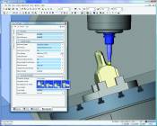
Step 4: Define the links within an operation and between operations. Multiple choices in a prioritized list takes the guesswork out of which linking methods are preferred by the moldmaker. Separate lists of preferences can be created for tool approaches, links within an operation, and links between operations.
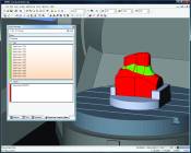
Step 1: Define the area to machine. A specialized feature contains information about the surfaces to machine (displayed in green) and the areas to avoid (displayed in red). Surfaces are easily added or removed and the toolpath updates automatically. Any number of these features can be created on a single model. Images courtesy of DP Technology.
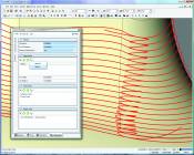
Step 2: Define the shape of the toolpath. With a variety of patterns available, the interface guides the user in choosing the best options for the most desirable resulting shape. The modular design of the software allows for easy expansion to other patterns in the future.
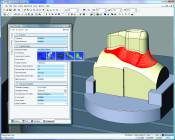
Step 3: Define the tool axis orientation. Separately definable tool axis orientations make it easy to try different tool orientations before deciding on the perfect cut. This is especially important when cutting tall cores or deep cavities with short, rigid tools. Full control is provided over the forward and backward tilt of the tool, plus angle limits allow an axis to be locked for 4+1 machining.
The challenge for moldmakers with multi-axis machines is to generate CNC programs that fully exploit the capabilities of these machines. The goal is to take full advantage of the additional axes of movement—whether on the table or in the tool head—in the most efficient manner while producing an outstanding surface finish.
In recent years, the growing complexity of simultaneous machine movement has made this difficult for CAM software systems due to both mathematical and technology challenges. The leaps in machine technology make it hard to synchronize the development of the technology to produce the efficient NC programs to run the machines.


In addition, any software product designed for multi-axis machines must be kept easy-to-use and error-proof. The smallest programming error can generate costly damages because the materials, high precision tools and accessories for these advanced machine tools are quite expensive.
Based on these premises, the challenge for CAM software developers is how to combine a set of powerful programming functions with a programming process that is easily understood by the user. The capabilities of these functions must be presented clearly, stepping the user through the programming process in order to avoid errors during the toolpath definition, while never becoming rigid or imposing limitations.
Old School Thinking
In order to provide users with a reasonable number of machining options, CAM software developers have almost always fragmented their 4- and 5-axis functionality into various dedicated functions for very specific types of toolpath. In fact, a point of pride for some CAM developers is the large number of functions available.
The price to be paid for this type of software development is that soon the system becomes a labyrinth of functions with the typical end user knowing and exploiting only a limited number of them. Busy CNC programmers cannot possibly be expected to memorize the purpose of dozens of functions in a CAM system. Programmers typically stick to the functions they know best and ignore the rest.
Four Easy Pieces
A new concept in highly advanced machining functionality is based on the idea that any 5-axis machining function—no matter how complex—can be defined with a few simple steps. When a moldmaker sits down to program a mold, he or she follows a time-tested method for deciding how to program that mold:
- What areas do I want to machine and in what order? Based on the complexity of the shapes involved, this can often be the most thought-provoking step for skilled machinists.
- What do I want the toolpath to look like on those areas? Do I want the tool to follow the parametric lines of the surfaces, cut in a back and forth or up and down motion, use the boundary of the surfaces as a guide, etc.?
- How do I want to orient the tool axis as it follows the toolpath? This is very important to the quality of the surface finish and whether a short, rigid tool is being used in tight spaces. Moldmakers require full control over the tool, which includes lead and lag angles to control the tilt of the tool. In addition, many machines have angle limits on how far the table or head can rotate and these limits must be taken into consideration. For example, the B-axis on a mill/turn machine will have limitations on how far it can rotate.
- How do I want the tool to transition from one cutting pass to the next? How do I want to control tool reposition moves at the beginning and end of the toolpath or when the tool must move between regions? Transition moves are critical in moldmaking to avoid witness lines and tool marks that will have to be polished out by hand later.
So then, if machinists follow a set of well-defined steps, why not create a CNC programming function that uses the exact same steps?
A New Way of Thinking
A better approach to CAM software development is to follow the logic that machinists themselves use when deciding how to machine a complex 5-axis part. Instead of fragmenting advanced 5-axis functionality, why not present programmers with a single programming process that is familiar and easy to understand?
This type of highly advanced technology would eliminate the conflict between powerful functionality and ease-of-use. By simplifying the methodology of multi-axis machining into one unique function, the user quickly becomes adept at exploiting the full power of the product. With this new approach to CAM functionality, maximum flexibility and compactness can be achieved in the field of 5-axis machining definitions.
One Programming Process = Programming Your Way
With a single function designed specifically for multi-axis machining, the user can create their own customized toolpath as a combination of available choices. In other words, by choosing any one of several available machining patterns and any one of the available tool orientation strategies, the user has multiple ways to machine the part.
For example, if the multi-axis function offers five different machining patterns and four different strategies to control the tool axis, the user has 20 ways to machine the part. Add to that the ability to lock an axis and 5-axis toolpath is quickly converted to a 4+1 application. Providing a variety of choices gives the user the creativity to compose any complex 5-axis function with few limitations.
To simplify matters even further, the interface should only display options that apply to the current work situation. For example, if a parametric machining pattern is chosen the user is prompted to select the drive surface and the parametric flow directions the tool should follow. If the user decides to change to a simple boundary offset pattern, the interface updates to display fewer options.
As the user chooses machining options, the interface needs to update immediately to guide the user in a logical manner through the programming process. This step-by-step guidance helps the user avoid errors in the toolpath definition without imposing limitations. If the user decides to change a previous option, the system responds by displaying a new set of choices.
Linking It All Together
For the smoothest surface possible, the manner in which the tool moves from the end of one feed pass to the start of the next requires finesse and control. Multiple options should be allowed for these feed links, using the cutting tool almost like an artist’s tool. Most CAM systems offer multiple linking options, so the next logical step is to let the programmer choose a favorite, a next favorite, and so on. That way, if the preferred linking method is not possible (due to a detected collision, out of limits error, and so on), the system can then use the next linking method preferred by the user.
For example, the user can give top priority to a linking method that keeps the tool on the surface the entire time, but if that method is not possible then the system can look at the user’s list of preferences to see how to behave next. As a second priority, the user prefers a link that uses a radiused move when the tool needs to lift off the surface and then return to the surface with a radiused move that is tangent to the next cut.
That way, the user can prioritize linking methods and there is less chance that the machining operation will fail or cause gouging because of an inappropriate move when the tool repositions. The same technology applies to retract moves when the tool needs to rapid from one position to another. Molds typically have obstructions that must be avoided, and giving the system a list of preferred linking methods takes the guesswork out of determining the best way for the tool to approach and detach from the part.
Feature-Based Five-Axis Milling
In addition to a compact and simplified milling function, the CAM system also must simplify the way users select areas to be machined. Machinable features, such as pockets and holes, are common in CAM systems for standard milling operations, but not common at all for complex milling.
A new type of freeform feature lets the user select and save the surfaces to be machined and the surfaces to be avoided as a single object. Knowing that different types of surfaces require different machining strategies, any number of these freeform features can be created on a single part model. The user can then select a single feature to machine an entire pre-defined area.
The design concept of consistency and ease-of-use needs to be extended so that the same interface is used for the freeform features and the 5-axis milling function. The user can then stay in a familiar environment without the need to open and exit multiple dialog boxes.
Crafting a Path Toward the Future
From the viewpoint of the software developer, creating a single milling function that meets the needs of moldmakers today and in the future requires an in-depth analysis of each step used in the process of generating multi-axis toolpath. It also requires real-world experience working with the types of multi-axis machines that are used every day on the shop floor plus the new technology being developed by machine tool builders.
This in-depth analysis has led to the conclusion that an adaptable multi-axis milling function must be composed of a collection of separate components that perform well separately and together. These components must be analyzed and tested to guarantee the complete interchangeability of any component at any step.
This analysis effort lends itself to a high rate of reliability in the resulting software, which ultimately benefits the user. Efficiency also is achieved because each component is created only once—eliminating the redundancy that occurs when advanced functionality is broken into a slew of machining functions.
The advantage to this type of functionality is that new machining patterns and tool orientation strategies can be added to the software at any time in the future as the technology for multi-axis machines advances. This type of thinking marks a departure from traditional CAM software development so that a CAM system can easily keep pace with the rapidly evolving technology in the moldmaking arena.
For more information from call (805) 388-6000, ext 143, e-mail ann.mazakas@dptechnology.com, visit www.dptechnology.com or visit www.moldmakingtechnology.com anytime.


Related Content

Tolerancing in Mold Design, Part 2: Using GD&T to Address Conventional Tolerancing Issues
Mold designers can achieve a single interpretation of workpiece functionality when following the American Society of Mechanical Engineers Geometric Dimensioning and Tolerancing standard.
Read More
The In's and Out's of Ballbar Calibration
This machine tool diagnostic device allows the detection of errors noticeable only while machine tools are in motion.
Read More
Tolerancing in Mold Design, Part 1: Understanding the Issues of Conventional Bilateral Tolerancing
Mold designers must understand the location, orientation and form limitations of conventional tolerancing before changing to another dimensioning system.
Read More
CAM Automation Increases Mold Production, Quality
Mold builder switches CAM software package after 20 years to take advantage of innovative programming strategies that reduce mold machining programming and processing times.
Read MoreRead Next

Reasons to Use Fiber Lasers for Mold Cleaning
Fiber lasers offer a simplicity, speed, control and portability, minimizing mold cleaning risks.
Read More
Are You a Moldmaker Considering 3D Printing? Consider the 3D Printing Workshop at NPE2024
Presentations will cover 3D printing for mold tooling, material innovation, product development, bridge production and full-scale, high-volume additive manufacturing.
Read More