Reverse Engineering: An Overview of the Options
The reverse engineering industry has come a long way in recent years and there are many options currently available that can be scheduled into a planned project with predictable and cost-effective results
The reverse engineering industry has come a long way in recent years and there are many options currently available that can be scheduled into a planned project with predictable and cost-effective results. Embracing these new technologies allows firms both large and small to meet the computing challenges that are pivotal to their competitive strength.
Three quarters of the manufacturing community today depend on some form of visual computing to help them design their products. Competitive marketplaces are forcing companies to look beyond better-known traditional methods to new technologies that allow for greater flexibility and bigger returns. One method companies are increasingly turning to is reverse engineering.
Reverse engineering is the process of capturing the geometry of existing physical objects and then using the data obtained as a foundation for designing something new. The new design could be a duplicate of the original or an entirely new adaptation. Recent innovations in this field continue to provide an even greater number of choices to fit most applications with fast, affordable and predictable results.
The first step to any reverse engineering project is gathering the geometric data of the part. There are a number of different methods used to do this, however, the existing model should dictate which technology is used. Traditional methods generally call for an engineer to sit down with a set of calipers and a ruler to gather a few particular measurements. This method is labor-intensive and often inaccurate. Also, organic shapes are extremely difficult to measure this way. Fortunately, with the advent of three-dimensional laser and optical scanners, advances in medical imagery and the development of coordinate measuring machines, reverse engineering has become easier and the results reliable and repeatable.
Data Acquisition
3-D data acquisition technologies used in reverse engineering are generally divided into two categories: contact and non-contact. Contact sensors include a wide variety of coordinate measuring machines (CMMs), while non-contact systems include optical (white light), laser (red light) and medical imagery. A third technology also worth mentioning is destructive scanning, a process that destroys the part while conducting the digitization.
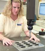
CMMs currently comprise the largest segment of data acquisition tools used by the manufacturing community. CMMs consist of a sensor equipped with a touch probe, which sends a signal when pressure is exerted on the end of the probe. Point-to-point CMMs are used to acquire specific points determined by the operator, while analogue CMMs follow the contours of an object automatically. Data acquisition is generally accurate but slow. Other drawbacks include the inability to use this technology on soft materials that will deflect when coming in contact with the probe and the inability to obtain information on objects that are smaller than the size of the probe.
Laser scanning (red light) is accomplished by using a laser device that collects range data. The most common method for acquiring range data is active optical triangulation. Range data is produced by placing a depth value on a regular sampling lattice from the surface of the object. Then, by connecting triangular elements with the nearest neighbors, a range image is created.
Generally, a 1-D or 2-D sensor is swept linearly across the object or circularly around it. As this is usually not enough information to describe the entire object being scanned, multiple passes must be made. Specially written algorithms are required to merge multiple range images into a single description of the surface. Although this technology has been around for nearly 20 years, the recent development of stable imaging sensors such as charged coupled devices (CCDs) and lateral effect photodiodes has increased its speed dramatically. There are several different types of scanners that accomplish this - their primary differences being the structure of the illuminant (typically point, stripe, multi-point or multi-stripe), dimensionality of the sensor (linear array or CCD grid), and the scanning method (move the object or move the scanner hardware).
Scanning Options
Optical scanners (white light) provide another method for reverse engineering. Digitization is accomplished through the use of a halogen lamp that projects a regular optical grid and a network of fringes on the surface of the object. A camera is used to record each image that the network produces. This method also employs the principal of triangulation with the information being sent to a CCD grid.
Optical scanners require being calibrated before use in order for the system to know where it is in 3-D space. These systems require the object to remain stationary while the scanner is moved around it. Optical scanning hardware also may be mounted onto a CMM. White light systems are only marginally affected by competing light in the room and the color of the object. In some instances, this could be an advantage over red light systems.
Optical scanners can produce greater resolutions than laser scanners, however, the greater resolution a scanner provides can also mean more noise in the data. Post processing of all data is an integral part of reverse engineering. Scanners are very operator dependent and require a trained eye to weed out stray points, correct overlapping or inaccurate data and to fill in missing information.
Technicians must follow particular guidelines and be able to predict how the digitization source will react and what kind of data will be produced when scanning the intended object. Gathering more points to describe an object does not necessarily mean that the information will be any more accurate. Sometimes, fewer, well located points that are truer to the surface of the object better serve the project than gathering more points that are not as accurate.
Destructive scanning involves a technique that alternately machines a thin layer from the part and then digitizes each layer using an optical scanner. This method captures the internal geometry of a part. However, the part is destroyed in the process. In destructive scanning, the part is embedded in a hardened resin, which maintains the integrity of the part throughout the machining process. Light parts are embedded in dark resins, dark parts embedded in light resins. The resin must completely encompass the part and fill all of the cavities in order to maintain integrity. Destructive scanning and medical imaging both require assembly of the individual digital slices obtained to recreate the object as a whole.
X-ray and MRI (magnetic resonance imaging) are two predominate medical imaging systems also employed by the manufacturing community. These systems provide the advantage of being able to capture the internal geometry of a part without coming in contact with the object being scanned. In the case of x-ray technology, an extremely high-powered x-ray source is projected through the object and collected on the other side. The collection sensor measures the amount of x-rays that were not absorbed by the part and outputs the information in a geometrical slice. MRI technology uses the same principal. However, instead of using x-ray, the system sends magnetic fields. Both methods can provide density information and are extremely helpful when looking for porosity in parts. Two of the biggest drawbacks to these systems are the high cost of setup and the additional safety precautions needed in order to use them. Additionally, the x-ray or MRI source may not be able to effectively pass through denser materials such as steel.
Finishing the Project
Once the geometric data of a part has been obtained, there are many different options available to continue the reverse engineering process. Most 3-D scanning systems readily translate scanned information to polygonal formats through a simple translation. STL, OBJ, DXF, ASCII, 3D Studio and others are typical outputs available. Rapid prototyping machines require only an STL file in order to manufacture a new part. Many CAM packages also will allow CNC milling directly from STL files.
If the desired result is to get a PRT file for use in a CAD program, then an IGES 128 (NURBS) surface must be created over the point cloud (scan data) produced by the scanner. There are currently many new products on the market that allow NURBS surface creation easily and quickly. The point cloud can be sliced in order to generate B-splines, and a surface lofted from there or a surface can be automatically generated directly over the point cloud. These new advances in reverse engineering software now make it possible to produce a CAD quality surface in a fraction of the time it took a short while ago.
The reverse engineering industry has come a long way in recent years and there are many options currently available that can be scheduled into a planned project with predictable and cost effective results. Embracing these new technologies allows firms both large and small to meet the computing challenges that are pivotal to their competitive strength. Recent improvements have opened the door to even the average user who may have never before considered using automated 3-D model creation from existing objects in product production.
Related Content
Mold Design Review: The Complete Checklist
Gerardo (Jerry) Miranda III, former global tooling manager for Oakley sunglasses, reshares his complete mold design checklist, an essential part of the product time and cost-to-market process.
Read MoreWhat is Scientific Maintenance? Part 2
Part two of this three-part series explains specific data that toolrooms must collect, analyze and use to truly advance to a scientific maintenance culture where you can measure real data and drive decisions.
Read MoreHow to Improve Your Current Efficiency Rate
An alternative approach to taking on more EDM-intensive work when technology and personnel investment is not an option.
Read MoreTolerancing in Mold Design, Part 2: Using GD&T to Address Conventional Tolerancing Issues
Mold designers can achieve a single interpretation of workpiece functionality when following the American Society of Mechanical Engineers Geometric Dimensioning and Tolerancing standard.
Read MoreRead Next
A Better Reverse Engineering Approach when Modifying Molds
Laser scanning services make good economic sense as they provide precise CAD data available for robot programming, which shortens the actual programming process.
Read MoreHow to Use Strategic Planning Tools, Data to Manage the Human Side of Business
Q&A with Marion Wells, MMT EAB member and founder of Human Asset Management.
Read MoreHow to Use Continuing Education to Remain Competitive in Moldmaking
Continued training helps moldmakers make tooling decisions and properly use the latest cutting tool to efficiently machine high-quality molds.
Read More


_300x250 4.png;maxWidth=300;quality=90)


.jpg;maxWidth=300;quality=90)


