
Quick Flow Analysis of Hot Runners
Quick flow analysis technology can improve the selection, design and troubleshooting of hot runner tools.


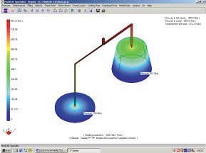
Figure 2: Runner balancing is a good and valid application area for the quick analysis technology.
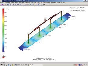
Figure 3: Quick analysis techniques can offer valid information to quickly determine the number of gates/drops required without doing extensive and time-consuming full-scale analyses.

Figure 1: Users quickly can obtain all of the major molding parameters such as pressure drop, temperature change, shear rate, runner volume, part cooling time, etc.
Leadtime and tool reliability/performance always have been the top priorities for both hot runner suppliers and moldmakers. The globalization of economy and the pressures from offshore competition make those issues more critical. People need new ideas and technologies to speed up and optimize the production of hot runners and molds to meet the ever-increasing demands for lower cost, higher quality and time to market.
Computer aided engineering (CAE) technology, e.g., computer simulation of injection molding or mold flow analysis, can offer valuable insight on the molding process and help engineers to design better hot runners and molds. In the meantime, the complexity and cost associated with most conventional flow analysis techniques often prevent a broad range of engineers from utilizing the advanced technology. Those programs mainly are used by expert users who have received extensive training and gained much experience in CAE analysis. Additionally, it could be very time-consuming to complete an analysis - even with an experienced analyst.


This article will present a proven alternative quick flow analysis technology and software for CAE experts and average engineers alike to carry out valid flow analyses for the selection, design and troubleshooting of hot runner tools.
Importance of Runner Design and Analysis
The importance of runner analysis on design and molding seems to have been long overlooked. When many flow analyses are carried out, the focus tends to be mainly on the part and cavity.
However, the runners play a much more significant role than many realize. The polymer melt always fills the runner system first after the machine nozzle, and then proceeds into the cavity. The flow and thermal history of the melt in the runner system will have a direct impact on how the cavity is filled and part quality. Also, hot runners add additional residence times to the melt. For low shot weight and temperature-sensitive materials, the longer residence time could impose the risk of thermal degradation to the resin. In many situations, the pressure drop in the runner system could be excessive and accountable for more than 50 percent - even more than 80 percent - of the total injection pressure. Apparently, if there is too much pressure loss in the runner system, there still would be enough pressure available at the gate to fill/pack the cavity. Poorly designed runner systems are often the root cause for many molding issues that could be resolved by only re-designing/modifying the runners without making any changes to other parts of the mold.
The very first step in designing any hot runner molds is to specify the most suitable gate type, nozzle size and manifold layout. Hot runner nozzles and manifolds usually are manufactured to different product lines according to their molding capability requirements and the inner runner bore sizes. There are strict relations between the runner sizes and the nozzle/manifold outside dimensions. In many cases, the changes to different runner sizes would mean that a different hot runner product line would be required, which inevitably will lead to many modifications to the mold. Therefore, it's very important to determine the correct hot runner system right from the beginning in the job quotation and tool design stage to avoid any undesirable costly changes later. The worst case could be that the mistake of putting an incorrect hot runner system on a production mold is not discovered until the mold is in the press.
One way to avoid these potential problems is through flow analysis, which can perform a molding test on the computer, check various design options, reduce design mistakes, highlight critical application areas and enhance the quality of runner system and mold.
Advantages of Quick Flow Analysis Technology
With the primary focus on hot runner applications, the new quick flow analysis technology and software offers several features and advantages.
Ease-of-Use
Targeting both advanced CAE analysts and broad plastics professionals (such as mold design engineers, moldmakers, project engineers, technical sales, molders, etc.), the software is simple to implement and use. There is no extensive training or prior experience required and no new difficult-to-understand terms or concepts introduced. Users literally can start doing actual flow analysis on their real jobs upon receiving the analysis software.
Speed
Any previously defined models are reusable and easy to modify. Users also can set up a library to store the frequently used system hardware and runner/gate configurations. With many unique and innovative analysis algorithms developed in the software, the users can analyze very quickly any type of hot and/or cold runner systems and get the results on all major parameters such as pressure drop, shear rate, runner volume, temperature rise, etc., in a matter of minutes. This quick speed makes it possible to obtain the critical data needed at any moment to make important decisions - even during a busy meeting with the customer or during an important conference call.
Low Cost
Being cost effective is another important feature for the quick flow analysis technology. The investment of implementing the technology could cost less than a simple two-drop hot runner system. Therefore, any company could easily afford and utilize this advanced analysis tool. Flow analysis really becomes accessible to all plastics engineers.
Handy and Practical
If the main goal is to specify and design the optimum hot runner system, the quick flow analysis technology will be very suitable, efficient and practical. It doesn't require any part CAD file or meshed model as a prerequisite to run an analysis; therefore, the unavailability of a good part CAD file doesn't prevent users from running analysis. This feature can be very handy, allowing the user to always be able to perform evaluations, even with very little information available, such as being given only the part's weight or its overall dimensions (which often is the case in the early job quotation stage).
One basic role for all of the CAE programs is to assist decision making. By doing quick and simple simulations, the user will be able to know the difficulty levels of the job in order to make important go/no-go decisions. The real-life applications have proved that it is possible to often make the same important engineering decisions by using the alternative simple/quick tool as you could with complex and costly technologies.
Accuracy
Clearly, the most important fundamental requirement for any CAE software is the analysis accuracy. Despite the simplicity of use and the fast speed in calculation, this quick flow analysis technology really is supported by many underlying innovative and sophisticated algorithms and techniques. The software takes many important and complicated factors into account such as non-Newtonian flow of the polymers, shear heating effect, nonsteady temperature fields and others. The quick analysis technology described here has been used successfully and tested in numerous real hot runner-molding applications. The market feedback is very positive.
A Win-Win Situation
It's a win-win for both hot runner suppliers and moldmakers to implement and utilize the quick flow analysis technology. As stated at the beginning, the tool leadtime and reliability/performance have always been the greatest concerns. Many moldmakers are lacking in specialized hot runner knowledge and rely almost entirely on their hot runner suppliers to select optimal systems during the mold design stage. In doing so, not only is valuable time spent in correspondence with suppliers, but also subsequent mold design changes become necessary each time a new or modified system is proposed. Changes to and miscommunication associated with hot runner tool designs are leading causes of longer mold design/delivery times.
Flow analysis can provide valuable data and give people the confidence to help make decisions more efficiently. Both hot runner suppliers and moldmakers can determine quickly the most suitable hot runner product line and understand each other's requirements and specifications, such as manifold layout, number of drops required, runner/gate sizes and other parameters. In other words, hot runner suppliers will know clearly what is the best system to supply for a given application, and moldmakers/hot runner users also will know clearly what system they need in order to integrate the right hot runner into their mold design from the start. This ultimately will help both hot runner suppliers and system users to reduce the leadtimes and improve tool quality.
Practical Applications of Quick Flow Analysis
Users can clearly see the benefits when they practically apply the quick analysis techniques to analyze real-life jobs.
Although quick and simple to use, the software and techniques basically can provide all of the major parameters for the application of hot runner molding (see Figure 1):
- Pressure drop
- Temperature change
- Shear rate
- Shear stress
- Optimal fill time
- Runner system volume
- Part cooling time
- Clamping force estimation
- Others
The way to apply the technology is quite versatile and flexible. The following are some examples of its practical applications in the industry.
Runner Sizing
Proper runner sizing is an essential part of hot runner system design, especially for demanding applications such as large size manifolds, high cavitations, difficult-to-process materials, heavy shot weights, thin wall parts, etc. It can be pretty tricky sometimes, as the requirements for runner sizes from different aspects of the application could be very different and oppose each other.
For example, when molding a 0.5-g thin part with a low-flow PC grade in a thirty-two-cavity tool, there are two different requirements for the runner sizes from two different aspects:
- Pressure drop
The tough material and relatively long runner lengths (remember it's a thirty-two-cavity tool) will mean high pressure drop; therefore, large runner sizes in the manifold system are desirable. - Residence time
The small shot weight would mean a long material residence time in the hot runner system and lead to the resin degradation problem. Therefore, smaller runner sizes are preferred. Now, what are the proper runner sizes that can generate a reasonable pressure drop without creating too much residence time? You can run many iterations quickly with different runner sizes and get the answer. Once the optimal runner sizes are established, the nozzle and manifold components/product line will be determined accordingly.
Another example is for making a PET (and some other material as well) preform tool. The shear in the runner system is so critical that it would decide the final part quality. You can establish the correct runner sizes easily to comply with the requirement of the critical shear data.
Proper Gate Size
The plastic experiences the most changes in the pressure, temperature, shear, etc., at the gate. Smaller gate sizes are desirable for less gate mark/vestige, but they also will shear the melt more and create excessive pressure drop. For certain materials such as many flame-retardant grades, if the shear rate is too high at the gate, the grades would be shear-degraded and lose their properties. The user can calculate accurately the shear rate and pressure drop data at the gate to detect any potential problems.
Although it's possible for moldmakers to modify the hot runner gate after a mold is built, too much change may affect, alter or even destroy the tool performance, as there are strict relations between the gate size, drop configuration, nozzle tip and temperature profile. Therefore, it's important to determine the proper gate sizes in the early design stage.
Runner Layout and Balancing
Balance flow is a basic requirement for all molding. One can efficiently use flow analysis to design runner systems to balance the flow artificially when a naturally balanced runner layout becomes impossible, such as on a five-, seven-, or ten-inch line cavity layout or on family molds (see Figure 2). Runner balancing is a valid application area for the quick analysis technology
Number of Drops
When you need to make a new tool, the number of drops and location are the first questions that both hot runner suppliers and moldmakers will consider, as they would have direct impact on the hot runner system and tool cost, design, cavity fill, part quality and machine requirements. The main factor in determining the number of drops needed is the plastic flow distance in the cavity and related pressure drop. The real practical applications have proven that the quick analysis techniques can offer valid information to help determine the number of drops required, although no extensive and time-consuming detailed analysis on the part is performed (see Figure 3).
Number of Cavities
To determine the number of cavities is another practical application for the software. For example, the user can determine quickly if it's possible to convert a lower cavitation tool to a higher cavitation (e.g., from eight cavities to sixteen) because of the introduction of additional runners and pressure drop, increased system volume and residence time, etc.
Cold to Hot Runner Conversion
In the real production environment, it sometimes is necessary to convert a cold runner mold to a hot runner mold when the production needs change. If the cold runner mold already is showing the concern of high injection pressure, then the use of a hot runner could impose an additional challenge, as the pressure drop in the hot runner system could be much higher if the proper care is not taken. Here, it is possible to calculate the pressure drop in the cold runner first and use it as the benchmark to determine the proper hot runner sizes so that the pressure drop in the new hot runner system could be the same or lower.
Material Selection/Comparison
When it is necessary to mold with a new material about which you have little knowledge, you can run some quick calculations, compare it with well-known materials, and get the valuable insight about the material's flow characteristics. This will eliminate guessing or uncertainty and provide confidence and knowledge about the job.
Molding Feasibility Studies
Is it possible to mold a polycarbonate part 50 mm x 10 mm with 0.4 mm wall thickness on a press with a maximum injection pressure of 30,000 psi? Is it possible to mold an auto part of 30 percent, glass-filled nylon 66 that is 1.5 m long, 3 mm thick on a machine.
Processing Window
The processing window allows users to analyze many what-if situations when designing a hot runner tool and predict what would happen if the use of molding parameters (i.e., melt/mold temps, fill speed) near their lower or upper limits becomes necessary.
Part Quality Studies
The calculated results from flow analysis often reveal many potential part quality issues. For instance, the software can calculate the temperature changes in cavity filling accurately. If the temperature of the melt flow front is too low, then the software would indicate possible weak knit lines for multigating or the parts with big openings. A high shear stress level around the gate may suggest a possible part crack issue when subject to high load in use.
Cycle Time Estimation
Molding cycle time is a critical economic element. The software can calculate the part cooling time accurately by considering material grade, part dimension, and melt/mold temperature, and quickly estimate cycle time by adding other factors such as mold open/close times, part ejection, etc.
Estimation of Machine Tonnage Requirement
The clamping force would be an issue when making large size parts. For example, to make a big tote part, it is possible to determine if you could only build a single cavity or make a two-cavity mold without exceeding the machine clamping force capacity.
Project Management
Everyone learns from past experiences. The software can serve as a handy project management tool. All of the important application data and project activities can be recorded and retrieved to help future jobs.
Troubleshooting
The quick analysis techniques can be used effectively to help troubleshoot many different molding issues. For example:
- With a high filling pressure issue on a hot to cold runner mold, it is possible to find out if the high pressure is mainly from the poorly designed hot runner, undersized cold runner, or the cavity itself in order to work on the right area to correct the problem. The user would know if modifying the gate alone could solve the issue or if he or she needs to do some major changes to the entire runner system. Perhaps there is really nothing wrong with the runner system - it's just an extreme situation and the user in fact needs a more powerful press.
- For an uneven fill problem on an unnaturally balanced cavity layout such as five-inline, it is possible to quickly find out the way to correct/improve the situation by testing different runner/gate modifications with the analysis on the computer.
- When having degraded materials on the parts, the software can be used to investigate if the shear rate at the gate is too high or if the long residence time actually is causing the issue and it is necessary to reduce the hot runner system volume.
- Sometimes it is important to know if switching the plastic material could finally solve certain molding issues (e.g., short shots) after all the possible changes have been made to the tool. The analysis software can find the answer without physically changing the material in the molding machine.
There are many other ways to utilize this quick, simple and cost-effective analysis tool. Users would benefit most if they could properly combine the quick analysis technology with practical experience.
Conclusions
A proven quick flow analysis technology and software is presented here that could effectively provide all of the critical parameters needed for both hot runner suppliers and moldmakers to specify/design the optimal hot runner system, enhance the mold performance and reduce the hot runner, mold engineering and delivery times.


Related Content

What is Scientific Maintenance? Part 2
Part two of this three-part series explains specific data that toolrooms must collect, analyze and use to truly advance to a scientific maintenance culture where you can measure real data and drive decisions.
Read More
The In's and Out's of Ballbar Calibration
This machine tool diagnostic device allows the detection of errors noticeable only while machine tools are in motion.
Read More
How to Select a Mold Temperature Controller
White paper shares how cooling channel analysis, which collects maximum pressure drop, total flow rate and heat dissipation, eases the performance evaluation of mold temperature controllers.
Read More
It Starts With the Part: A Plastic Part Checklist Ensures Good Mold Design
All successful mold build projects start with examining the part to be molded to ensure it is moldable and will meet the customers' production objectives.
Read MoreRead Next

Trends in Hot Runner Technology
Quality, performance, maintenance and flexibility are driving today’s hot runner technology.
Read More
How to Use Strategic Planning Tools, Data to Manage the Human Side of Business
Q&A with Marion Wells, MMT EAB member and founder of Human Asset Management.
Read More
Reasons to Use Fiber Lasers for Mold Cleaning
Fiber lasers offer a simplicity, speed, control and portability, minimizing mold cleaning risks.
Read More