Printing Vacuum Forming Tooling with FDM
Combining the advantages of 3-D CAD and FDM technology, vacuum forming can be completed quickly, efficiently and cost effectively


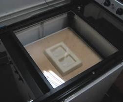
The vacuum forming machine is shown (above). The top of the machine heats up the plastic sheet so that it will form around the mold. The vacuum pump is underneath. Photos courtesy of Dimension, Inc.
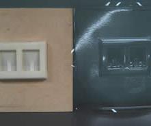
The mold is shown on the left. The vacuum formed-sheet on the right can now be cut as needed for a finished product.
Vacuum forming involves heating a sheet of thermoplastic to forming temperature, drawing the sheet onto a tool (or mold) by applying vacuum pressure between the tool surface and the sheet, and finally, removing the model through reverse air pressure when the plastic has sufficiently cooled.
This process is relatively inexpensive when compared to other plastic molding and forming methods. Common applications include packaging, internal automotive components—such as interior panels and instrument panels—point-of-purchase displays, blister packs and orthopedics.


Vacuum Forming: A Few Considerations
There are a few things to keep in mind when choosing vacuum forming for manufacturing. First, the process does not support variable wall thicknesses, and a part’s geometry must allow a straight pull (no undercuts or side action). Also, keep in mind that the side of the sheet of plastic that touches the tool will be the more defined side of the final model or final product.
Finally, consider what means are available to construct the tooling. For many years, vacuum forming was cumbersome due to the time and effort it took to create the tooling onto which the thermoplastic sheets are molded. Up until the mid-1980s, designers used primarily craftsman to hand-build tooling. The tooling was fashioned out of wood or other materials sufficient to withstand the heat and pressure of the vacuum process. After the model was formed, multiple holes had to be drilled through the tool to allow for the vacuum pressure required during the forming stage. In the end, handcrafting molds proved to be very time consuming and not well suited for situations where multiple design iterations are needed to produce the desired tool.
Tooling Made Easy
Fortunately, the advent of FDM® (fused deposition modeling) technology to construct the thermoforming tooling has made vacuum forming a more efficient and increasingly cost-effective process.
FDM is a 3-D printing/rapid prototyping (RP) process.1 The FDM process for vacuum forming begins by creating the design with 3-D CAD. The file is then sent to the 3-D printing or FDM system that prints the tooling from engineering thermoplastics, such as ABS, sulfones and polycarbonate.
FDM systems dispense two materials: one for the model and one for the model’s support structure. The material is stored on a spool of plastic filament contained in a cartridge. The filament is fed into an extrusion head and heated to a semi-liquid state. The head then extrudes the material and deposits it in layers as fine as 0.005 inch (0.127mm) thick. Unlike other rapid prototyping processes, 3-D printers using FDM require no special facilities or ventilation, and involves no harmful chemicals or byproducts.
The low pressure and temperature of the forming operation facilitates the use of tooling constructed from many materials. For large production runs, vacuum forming tools are machined from aluminum. Although the life of tools constructed with ABS, polycarbonate (PC) or polyphenolsulfone (PPSF/PPSU) will not equal that of an aluminum tool, these three materials are ideal for prototyping and short-run manufacturing. Depending on the FDM material used for the tool and the thermoplastic used in the part, tool life can range from 100 to 1,000 parts.
Advantages
FDM eliminates much of the time and labor associated with machining of vacuum forming tools. There is no tedious handcrafting involved in the process—the 3-D data is processed in minutes and tool construction can begin immediately after tool design. Automated and unattended FDM or 3-D printing operations eliminate the time needed for fixturing, setup and operation of CNC milling machines.
Another advantage of FDM is the tools it creates are inherently porous, which eliminates the time needed for drilling vent holes that are necessary for other vacuum forming tools, while improving part quality with an evenly distributed vacuum draw. Using modified build parameters, FDM tools offer excellent feature detail and fast vacuum cycles while eliminating the labor and time for drilling vents.
Combining the advantages of the 3-D CAD and FDM technology, vacuum forming can be completed quickly, efficiently and cost effectively.
Applications
Packaging is the leading application for vacuum forming. The clear plastic bubble (blister pack) that contains a product is vacuumed formed. The disposable plastic lid on a coffee cup is vacuum formed, as are the plastic and foam containers used in delicatessens and fast food restaurants.
While the packaging industry is the leading consumer of vacuum formed parts, the applications extend across many product types and throughout many industries, such as:
- Automotive applications including instrument panels, wheel covers and door liners.
- Aerospace covers and cowlings.
- Boat hulls: the marine industry shows that vacuum formed parts can be large.
- Electronics applications including anti-static conveyance trays.
- Custom machinery covers and shrouds.
Consumer Packaging Development Success Story
Saving time and money are desirable outcomes, but phenomenal gains arise when the tool design process is changed through the incorporation of FDM. An example of what FDM and vacuum forming have done to streamline package development efforts can be seen clearly in one mass-market, consumer goods company.
Prior to the company implementing FDM technology, it required a full day of labor just to complete the task of drilling of vent holes in the tool. Many of the tools used were multi-cavity, forming a dozen or more parts in one cycle. With all of the cavities, there are 1,000 to 2,000 vent holes to be drilled. With FDM tooling, this labor-intensive operation was eliminated.
However, the biggest benefit the company enjoyed since incorporating FDM is not in labor savings, it is in process improvement. The typical product development cycle has package design and development as one of the last tasks before product launch. Being last meant that any delays in prior processes reduced the time available for package design. With FDM, the company now produces prototype products and prototype packing well before final design release. Removed from the critical path, there is more time to design and prototype innovative packaging. The results are less time pressure on the package development team and more creativity in package design.
For consumer products that are picked from a retail shelf, package design is often the key difference that motivates the consumer to buy a product. FDM for vacuum forming enables the company to stand out on product shelves.
Choosing the FDM Technology That’s Right for You
The first question to ask is what type of thermoforming material will be required in manufacturing. If you determine high-temp sheet materials—such as polypropylene or polyethelyne—are required you should consider a high-end FDM system that can build tooling in multiple high temp materials such polyphenolsulfone.
If your vacuum forming project calls for lower temperature materials—such as PVC or styrene thermoplastic sheets—a 3-D printing system is likely your best option. The 3-D printing system’s ABS tools will perform well for these lower temperature applications and the systems tend to be significantly less expensive than high-end FDM systems.
References
1 Patented by Stratasys, Inc.


Related Content

Mold Design Review: The Complete Checklist
Gerardo (Jerry) Miranda III, former global tooling manager for Oakley sunglasses, reshares his complete mold design checklist, an essential part of the product time and cost-to-market process.
Read More
Tolerancing in Mold Design, Part 1: Understanding the Issues of Conventional Bilateral Tolerancing
Mold designers must understand the location, orientation and form limitations of conventional tolerancing before changing to another dimensioning system.
Read More
Mold Innovations Power Unique Auto Lighting Elements on Hummer EVs
Diamond machining, electroforming of micro-optical inserts and modified latch-lock system help injection molds produce unique forward lighting elements.
Read More
Tolerancing in Mold Design, Part 2: Using GD&T to Address Conventional Tolerancing Issues
Mold designers can achieve a single interpretation of workpiece functionality when following the American Society of Mechanical Engineers Geometric Dimensioning and Tolerancing standard.
Read MoreRead Next

Digital Manufacturing’s Role in Today’s Mold Shop
Mold manufacturers are seeing the benefits that low-volume digital manufacturing services can provide as a non-competitive alternative.
Read More
Are You a Moldmaker Considering 3D Printing? Consider the 3D Printing Workshop at NPE2024
Presentations will cover 3D printing for mold tooling, material innovation, product development, bridge production and full-scale, high-volume additive manufacturing.
Read More
How to Use Strategic Planning Tools, Data to Manage the Human Side of Business
Q&A with Marion Wells, MMT EAB member and founder of Human Asset Management.
Read More