
Cleaning a Flashed Hot Manifold, Part Three
Cleaning nozzles and manifolds, electrical boxes, assembly and final check.


Editors note: This is part three of a three-part series. You can find the links to the entire series below.
Part 1: A look at in-house and outsourced cleaning
Part 2: Steps of a typical clean and rebuild of an encapsulated system
Part 3: Cleaning nozzles, manifolds, electrical boxes, assembly & final check
We left off last month with all 16 nozzles removed from the manifold (with the tips protected by tape) and still wired to the electric box. This arrangement allows the nozzles to be cleaned yet still connected, which cuts about three hours of rewiring time from the process. It also means that you must move the nozzles and electric box around as a group so care must be taken not to damage the housings, heaters and wire connections. Utilize a plywood board/tray large enough to carry the nozzles and electric box and move them to another area of the bench—preferably close to a vice equipped with soft jaws.
While we clean the nozzles, the ultrasonic is busy cleaning the retainer plate, which should not take more than an hour or two to remove all traces of degraded plastic—eliminating this worry during assembly.


Cleaning Nozzles
The degree at which a nozzle needs to be cleaned is dependent upon the clearance around the nozzle body and the cavity insert along with the sealing/stacking surfaces of the components. The entire nozzle does not need to be spotless with all traces of plastic removed to be reinstalled and seated properly. This can be accomplished a number of ways, depending upon the type of nozzle and how it is heated.
All that is necessary is to:
- Clean the nozzle housing front and back, and to remove enough plastic around the nozzle body so they can easily enter the back of the cavity without interference.
- Plastic around the front tip must obviously be removed if it stacks and seals against the back of the cavity gate insert.
- Clean the back of the nozzle seats and run them over a medium Norton stone to make sure they are flat and smooth. If a depression is noted then this must be measured to ensure the depth of the depression is no greater than .001 or a slow leak could occur here (see Photos).
Cartridge Heated Nozzles
If the nozzle has an internal cartridge heater that isn’t stuck, simply pull it out (make sure it is numbered) and use a soft wire wheel to clean off whatever plastic is on the body, taking care not to damage or reconfigure the tip.
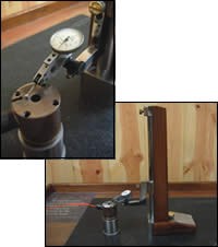
Checking the surface flatness of the back of a typical heater nozzle with an indicator. A steel bushing ground flat makes a convenient base to hold the nozzle. Images courtesy of MoldTrax.
Some technicians like to burn the excess plastic off nozzle bodies with a torch, before disassembly and while the manifold plate is standing up on the bench. If this is your preference it is advised to use a controller (versus a torch) to heat up the nozzles just enough (usually around 250 to 300 degrees) to easily remove the plastic, which makes this operation safer and without stinking up the shop.
If the heater cartridge is stuck, then you can either drill it out (thus scraping the heater) or leave it alone and clean off the nozzle body with a brass pick/scraper. You also can clamp it up in a vise (soft jaws) and use a wire wheel in an air drill.
Standard cartridge heaters are typically .005 smaller than the nozzle bore, but if not cleaned out periodically will stick hard. If you do have to drill it out, use the next standard size smaller bit, taking care not to scar up the bore walls. Resist the temptation to perform this operation by eye at the bench with a hand drill, instead use a lathe to do it right.
The objective is to drill out all but the outer skin of the heater allowing you to slip a prick punch behind the skin, bend it in far enough to grasp it with needle nose pliers, hose it down with WD-40 and work it out. A time-consuming task that is best prevented through regular cleanings and the application of an anti-seize product like a release and transfer fluid before installing heaters.
Cast-In Heated Nozzles
These are more of a pain to clean because of the attached heater/thermocouple wires that should not be removed for normal maintenance. They also require great care not to poke holes in the embedded heaters or to damage the leads and (ceramic) connectors. Never use a torch on these types of nozzles and only clean what is absolutely necessary to reinstall the nozzles.
Banded Heater Nozzles
These are great simply because the heaters and thermocouple wires are usually easily removed, making cleaning the body much easier via ultrasonics. Any time a component can be cleaned in an ultrasonic tank, the process will be faster. The only problem usually stems from removing the thermocouple.
Some brands require you to straighten out the tip before you can slip it through the nozzle, which can stress crack and ruin the thermocouple. If this is the case, and the manifold is extremely time-consuming to work on, then spend the money and replace all of the thermocouples so as not to risk creating an opportunity for them to fail—negating all of your labor hours.
Manifolds
Once the nozzles and manifold are cleaned, run a stone over the manifold (medium Norton stone) looking for burrs and hobbed areas around the seal points. If you have a rock (granite surface plate) handy, you could quickly give the manifold, bridges or crossovers a quick check for flatness.
Judging manifold flatness and seal area hobbing/pitting is usually determined by how the nozzles are sealed against the manifold. Nozzles that are independently bolted to or screwed into the manifold are more forgiving of slight imperfections than those counting on only an expansion fit between plates and spacers to seal.
But mostly it will be dependent upon the number of white shirts breathing down your neck to get the mold back into production as to deciding whether or not action should be taken at that time. As a rule, if you can rock any of the components on a surface plate over .005, then it is time for a dusting.
A Word about Electrical Boxes
Most hot runner electrical boxes sit on top of the mold directly over the manifold and are usually bolted directly to the top of the plates with a pocket cut out to route the wires through and into the box connectors.
The problem with this setup is this continually abused electrical box now also acts as a chimney for the vent residue/gases. Even though the box access panels are normally sealed, the gases seem to find their way inside the boxes—coating everything in sight.
It has been said by some electricians that this gummy mess can cause the connections to short out on occasion. It also has been said by others that only certain residues will support an electric current, but no one seems to agree on exactly which ones.
In the meantime, set your electrical boxes on a 1-inch spacer that has been slotted all the way through so that the gases can escape to the atmosphere, and install a rubber gasket in the bottom of the box to feed the wires through, thus keeping the inside of the box and connectors cleaner.
Assembly
Once the plate counter bores, nozzles and manifold are clean, stoned and wiped down, it is time to reorganize things and get ready for the assembly stage. Wipe off the bench top, sweep the resin off the floor and put away your cleaning tools.
Lay the manifold retainer plate face down on some rails (parallels) to keep the nozzle tips from contacting the bench top as they are placed in the pockets. Bring the nozzles (still connected to the electrical box) over to the plate and lay them out as they go in.
Install the nozzles, making sure they are bottomed out in the pocket. Once all of the nozzles are in position, refasten the electrical box. Using depth micrometers, verify all nozzles are the same height (usually within .002). An old support post ground to the same height the nozzles should be when installed as a reference is recommended.
When you are satisfied, set the manifolds back onto the nozzles. You could check the manifold height at this stage for flatness, but it’s more accurate to bolt them down to the proper torque value first, and then measure. It is recommended to tighten the manifold bolts starting from the inside working in a cross-over pattern to the outside. Apply a good anti-seize to all bolts on the threads and under the bolt heads. Flatness should be no greater than .003 across the manifold.
After this final step, hook up the controller and check for any dead shorts and heat up to about 200 to 300 degrees to make sure everything works properly before bolting the retainer plate on and reassembling the “A” side. If you are going to install the “A” side cavity plate at this time, make sure the manifold and nozzles have cooled down to match the temperature of the cold (room temperature) cavity plate.
If all is well, install the retainer plate and remaining components using anti-seize on everything in sight.
Final Check
A typical procedure includes:
- Running water through the manifold plates to keep things from overheating;
- Turning on the controller and ramping up heaters to processing temperature;
- Verifying that all heaters and thermocouples are working properly;
- Letting set for 15 minutes then shutting off controller;
- Letting water continue to flow and cooling off plates; and,
- When manifold “A” side plates are cooled to same temp as “B” half assemble the mold.
After the final check is completed, fill out any required documentation, change the mold status and relax a bit because the next encapsulation is right around the corner.
Read Part 1 of this series: A look at in-house and outsourced cleaning


Related Content

Questions and Considerations Before Sending Your Mold Out for Service
Communication is essential for proper polishing, hot runner manifold cleaning, mold repair, laser engraving and laser welding services.
Read More
Laser Welding Versus Micro Welding
The latest battle in finely detailed restoration/repair of mold materials.
Read More
Precision Welding Services Offer Rapid Turnaround Mold Repair and Reduced Molder Downtime
X-Cell Tool & Mold relies on outsourced, high-quality welding repairs from Lewis-Bawol Welding to ensure its customers' molds are back in production quickly and affordably.
Read More
Products and Services for Multiple Moldmaking Needs
New year, new technology roundup! Featured here is a collection of product offerings, from profile milling cutters to industry-specific CAD/CAM software to innovative hot work tool steels.
Read MoreRead Next

Cleaning a Flashed Hot Manifold, Part One
A look at in-house and outsourced cleaning.
Read More
Reasons to Use Fiber Lasers for Mold Cleaning
Fiber lasers offer a simplicity, speed, control and portability, minimizing mold cleaning risks.
Read More