Part I: Spindles and Their Relationship to High-Speed Toolholders
There are many machine tool spindle options for high-speed machining. This first part of a two-part article illustrates the pros and cons about the many options available before making a decision.
In order for mold shops that are machining steel to remain competitive in today's global manufacturing environment, they must consider high-speed machining and/or hardened steel machining. Such machining will allow the mold shop to cut down production time dramatically by reducing a great deal of EDM time, and the labor intensive polishing time. This reduction in labor and time cost will allow mold shops to be competitive.
There are four basic hardware components that must be considered in high-speed machining center applications:
- The machining center
- The toolholder
- The cutting tool
- The machine tool software
In order to make educated decisions about the proper machining center equipment to purchase for high-speed machining, it is important to consider the connection between the machine tool spindle and the toolholder. The options for this spindle connection are many, and include CAT vs. BT tapered tools, and dual face contact options. Once the mold shop has decided on the appropriate spindle, it must decide what issues are important to it when choosing toolholders. In order to do that, the mold shop must understand the essential components of a toolholder that is going to be run at high speeds (rigidity, accuracy and balance). It is necessary to examine all toolholder and spindle components in order to clear up misunderstandings about spindle and toolholder options in moldmaking applications.
What Is High-Speed Machining?
When looking at the relationship of balanced tooling in conjunction with high-speed spindles, it is important to define the speed or rpm, which constitutes high-speed machining. There are several different views throughout the industry. The first definition is the market survey of horsepower vs. rpm, which states that high-speed machining is: 10,000 rpm at 50 horsepower, 15,000 rpm at 40 horsepower, 30,000 rpm at 30 horsepower, 40,000 rpm at 15 horsepower, and 60,000 rpm at 10 horsepower. The second definition defines high speed by commonly applied taper sizes; 50 taper at 10,000 to 15,000 rpm, 40 taper at 15,000 to 25,000 rpm, and 30 taper at 30,000 rpm and up.
Finally, the international organization for standardization ISO 1940 specification first edition printed May 1, 1973, states that at approximately 8,000 rpm is the speed that requires toolholders to be balanced.
Consequently, there is not one good solid definition for high-speed machining. Typically, high-speed machining has been thought of as high speeds and feeds with a low depth of cut, which results in fast metal removal rates. In fact, many feel that high-speed machining should actually be defined as high-efficiency machining. This means the amount of time that it takes to actually machine the workpiece determines high-speed machining. This definition claims to be independent of machine rpm; however, machine rpm usually must be on the higher side in order to maximize high-efficiency machining. Ultimately, the goal of utilizing high-speed machining is to create a highly efficient machining environment.
The actual effect on the machine spindle is the true indication of high-speed machining. Since all spindles and machines are not built in the same fashion, one must consider many elements of the actual construction of the spindle. For instance, does the spindle offer dual face contact? How massive is the spindle in relation to the mass of the toolholder? How is vibration affecting the spindle and the cutting tool at the machined surface? These factors all influence the effect of centrifugal forces on the machine spindle at high rpms.
The centrifugal forces created at high speeds cause us to have to think more about the tooling we put in the spindle. According to ISO 1940 as mentioned earlier, 8,000 rpm is the approximate speed at which unbalance begins to have adverse effects on the application. At 8,000 rpm the centrifugal forces generated by the spinning motion of the spindle begin to show several effects.
First, the spindle begins to expand at 8,000 rpm, which can diminish contact between the machine spindle and toolholder taper, resulting in a loss of rigidity. Second, any unbalance in the toolholder causes an uneven whipping effect that stresses the spindle bearings, causing premature failure over time. Third, unbalanced toolholders at high speeds cause vibration to adversely affect the finish and tool life, which ultimately leads to out-of-tolerance parts. Finally, higher rpms also can lead to a toolholder being sucked up into the spindle in "Z", and this may cause your workpiece to be machined incorrectly.
In metal cutting, unbalanced centrifugal forces and the resultant vibrations increase with the square of the rotational velocity. The force produced by an unbalance at 10,000 rpm, for example, is 100 times greater than one produced at 1,000 rpm.
Toolholders
In order to combat the effects of centrifugal forces at high speeds, machine builders and tooling manufacturers have developed a number of different spindle options. For years, machine tool manufacturers have created spindles to accept toolholders with a long 7/24 taper. These tools are known as either CAT or BT toolholders, and they range in many different sizes (typically 30 being the smallest and up to 60 being the largest). As machine spindles began to increase their maximum speeds, it was necessary to expand on the design of the toolholder and their shanks. Consequently, dual face contact tools were designed. This allowed the toolholder to maintain taper and the additional face contact to the machine spindle. The idea behind face contact is to allow for a higher level of static stiffness, taper contact, and control of the "Z" dimension at higher rpm's. Face contact tools have included HSK, KM, NC5, and 7/24 taper dual contact holders.
Today, the most common spindle offered on machining centers is still the 7/24 steep tapered spindle (BT, CAT or ISO). The larger the number behind the CAT or BT, the larger the holder is. In other words, BT30 is a small, light toolholder, and CAT60 is a very large and heavy toolholder. When standard BT and CAT tapered tools are inserted into the spindle of a machining center, a gap exists between the spindle nose face and the tool flange. In the United States, most machining centers use the CAT version of these 7/24 tapered spindles (CAT tapered tools were developed by Caterpillar). In Japan and Europe, most machining centers use the BT version of the 7/24 tapered spindles.
There are five distinct inherent differences between BT and CAT tapered tools. The first difference is that the BT shank holder calls for a ground ID in the retention knob cavity. This accepts a retention knob with a ground pilot underneath the shoulder of the knob. This is important because it keeps the pulling force of the spindle on the centerline of the toolholder to minimize any error in the fit between the toolholder taper and the machine spindle. Also, a retention knob with a ground pilot will repeat to the same position when you remove it and then replace it again. A CAT shank retention knob will not. This is a benefit in maintaining balance in high-speed applications.
The second difference is that the BT shank holder is manufactured for symmetry. Both drive keys have the same width and depth. A CAT shank toolholder has drive keys that vary in width and depth, and, therefore, a correction mark must be made in the smaller keys to compensate for the difference. This makes the BT shank toolholder easier to balance.
The third difference is that the CAT shank toolholder is governed by the ANSI standard, which calls for a relief cut under the flange of the toolholder of 5/8" width. This is a requirement so that there is no interference with carousel-type tool changers. This specification unfortunately weakens the design of the CAT shank. Without the relief cut, in the case of BT, the toolholder can be shortened and a thicker diameter can be maintained under the flange for increased rigidity.
The fourth difference is that all of the dimensions on the BT shank toolholder are in metric. This includes the threads in the retention knob cavity, and the keys. The fifth and final difference is the slot in the flange of the BT shank toolholder is off-set, plus the flange is thicker. On the CAT shank toolholder the slot in the flange is centered. When users demand high-speed and high-precision machining capabilities on their machining centers, the following problems become clear on 7/24 taper standard tooling:
- Due to the centrifugal force at high spindle speeds, the spindle taper expands, and the tooling is pulled farther up into the spindle. This causes the z-axis tool length to vary. If the tooling is pulled up too far, it can be difficult to remove from the spindle on machines with automatic tool changers (ATC).
- Standard 7/24 taper tooling encounters vibration in the spindle at the high spindle speeds. This is created due to a loss of taper contact at high rpms.
- The repeatability of ATC is poor as only the taper is in contact with the machine spindle.
- 7/24 taper is too severe to run at very fast speeds and struggles to maintain a good finish particularly when heavy milling. Due to the tool taper length, the location of the front end bearings of the machine spindle are located far away from the spindle face (in comparison to short 1/10 tapered tooling), which limits the ability of the spindle.
There are not only problems with the tool interface itself, but also with pull stud pulling mechanisms. Most machining centers adopt several disc springs, and the result is that over a number of years there is a reduction in the pulling force.
In the ordinary spindle clamping with disc springs for 7/24 taper, as the holder is clamping with only the disc spring force, it causes fretting corrosion due to the axial vibration if the excessive cutting force is loaded. Besides, when it's unclamping, the disc spring force plus extra force is required and it causes overload on the bearings. Since the disc springs are always contacting each other, there are some problems with repeatability, wear and durability, especially on the machine with center-through coolant capability, since these machines cannot perfectly prevent the coolant from leaking. Therefore, the very front end of disc springs might become damaged with rust and eventually break. Even if they don't break, chances are the pulling force will be decreased substantially.
HSK spindles
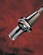
With the downfalls listed above with standard 7/24 tapered tooling, the industry was forced to offer different spindle options for higher rpms. One of the more common tapers now offered for high-speed machining is the HSK spindle. HSK was originally developed in Germany, and it contains a short 1/10th hollow taper. It is able to provide both taper and flange contact. HSK comes is a variety of forms and sizes. It comes in forms A through F (each form has slight differences based on different applications and balance specifications), and different sizes and weights (typically HSK32 up to HSK100, with the 32 or 100 being the diameter of the flange of the toolholder). The way in which the HSK toolholder is drawn into the machine spindle is very unique. There are no pull-studs necessary on HSK toolholders. Basically, an expanding mandrill is inserted into the ID of the HSK toolholder. It expands to create contact between the toolholder and the machine spindle, and then it draws the toolholder up into the spindle of the machine.
The HSK toolholder/machine spindle creation has addressed a number of the drawbacks related to the 7/24 tapered tools when run at high spindle speeds. First of all, the 1/10 taper keeps the bearing of the machine spindle compact and close to where the machining is actually being done. Secondly, the hollow taper of HSK tooling allows for the taper of the toolholder to expand with the machine spindle as it expands due to centrifugal forces created by increased spindle speed. In other words, the hollow taper expands at a higher rate than that of the machine spindle, therefore creating outward pressure on the ID of the spindle and maintaining quality contact between the taper and the machine spindle. Third, the face contact of HSK tooling to the machine spindle face creates a higher static stiffness due to the combination of both taper and flange contact. Finally, the flange contact also allows for "Z" dimension to be better controlled due to the fact that the toolholder cannot be sucked up into the spindle farther when run at high rpms.
1/10 Short Taper, Double Face Contact
The second dual face contact spindle option developed for high-speed machining is a spindle developed in Japan. This system is quite popular in Japan, but it is not as popular throughout the United States. However, the 1/10 short taper, double face contact system does address a number of the problems related to standard 7/24 tooling when running at high spindle speeds.
Similar to HSK, the taper angle is a 1/10 taper, which provides superior static stiffness and torque transmission characteristics. The tooling also has a short taper. This allows the bearings at the front end of the spindle to be positioned closer to the tool side, thereby greatly improving the stiffness of the spindle system. In addition, this also shortens the ATC time. The tooling is not hollow like HSK. Instead, it has a sliding taper mechanism built into the taper of the toolholder. This sliding taper mechanism exhibits superior dampening performance as proved in many tests by Japanese Universities. It was found that the added static stiffness and dampening effect of the tooling created a stable chattering environment on the workpiece. It also was found that high dampening performance allows high-speed, high-feed operation and also greatly extends the cutting tool lifespan.
Also, like HSK, the tooling uses the double face contact system, which achieves simultaneous taper and flange contact. This improves stiffness and torque transmissibility and also increases the tool radial repeating accuracy and run-out accuracy. The double face contact system offers superior static and dynamic run-out accuracy (run-out accuracy when the tool is mounted with the phase changed by 180 and run-out accuracy at high spindle rpm). A higher run-out accuracy also extends the cutting tool life by a wide margin. The important point here is not simply that double face contact improves repeat accuracy and run-out accuracy, but that double face contact holds the run-out accuracy of the spindle flange with respect to the machining center's spindle taper as close to zero as possible, thereby stabilizing repeat accuracy and run-out accuracy. Of course, the method of holding the cutting tool also has a huge effect on run-out.
As mentioned earlier, an ordinary 7/24 taper tool is pulled up in the Z axis direction when run at high spindle speeds. Hence, for a double face contact tooling system of taper and flange, a mechanism that can absorb the minute error of the gauge line has to be created somewhere on the tooling itself. The 1/10 short taper, double face tooling system solves these problems with its sliding taper mechanism (when tool clamping occurs, the taper cone - which has a slot - is compressed following the internal taper of the spindle, and shifting in an axial direction - absorbing gauge line error). Thanks to this system, the manufacturing of both the machine spindle and the tooling can be simplified, and the tools can be interchanged more flexibly without worry of the Z axis dimension being compromised.
Due to the short 1/10th taper design and face-contact ability of this toolholder option, many comparisons have been made between it and HSK. They are similar in the advantages they provide over 7/24 tapered tools, such as higher static stiffness, the ability to maintain face and taper contact, and the control of potential Z axis growth. One of the obvious differences, however, is the fact that HSK does not have the dampening mechanism that the sliding taper provides. Also, the cutting tool in a HSK toolholder must extend a bit farther from the spindle face of the machine since the body of an HSK toolholder is hollow, and none of the cutting tool shank can be placed inside the hollow portion of the toolholder.
7/24 Dual Face Contact Designed Spindle
A third spindle option that is available on many machining centers is the 7/24 dual face contact designed spindle. This spindle design is fast catching on throughout the world in order to address high-speed machining. It has become so popular so fast because it takes standard 7/24 tapered tooling, and/or special tooling that can provide face contact. This allows the end users to decide if they need special tooling or not. Often times, people ask why 7/24 tapered tooling did not always have the ability to get face and taper contact. The answer is quite simple. Standard 7/24 tapered tooling is solid, and it is very difficult to maintain the relationship between two solid surfaces (in other words, taper and flange contact). In addition, this double face contact tooling system is no different in terms of the taper angle (7/24), taper length, front end bearing location of machine spindle, and pull stud clamping mechanism. Nothing has changed on the machine spindle except the flange contact. Also, at high rpm's there is spindle expansion, and with solid toolholders there is no real advantage (except for better control of the Z axis) to have face contact since the spindle will lose the all-important taper contact.
Consequently, in order to make full use of the 7/24 dual face contact design with internal springs, an expanding taper sleeve has been developed. The new expanding taper sleeve is a unique triple contact tooling system, which has been developed to achieve improved cutting capability and better machine finish accuracy on 7/24 taper machining centers. This is not only to improve tool change repeatability, but also to prevent the tool from jamming in the machine spindle at the high-speed rotation. The machine tool's cutting capability is maintained even when the pull stud pulling force reduces after several years of use. The system consists of a main body with an internal taper configuration housed inside a taper cone. The taper cone is shaped to conform to a 7/24 external taper. This taper cone is pre-loaded on the body with the disc springs. The system defines the pre-load, ensuring a well-balanced fixed contact ratio at taper and flange (ninety percent: ten percent).
A standard BT/IT taper normally achieves excessive contact, and this sometimes causes a problem when releasing the tool at the ATC. However, the system solves the problem with its unique configuration. The combination of the taper cone and disc springs creates a dampening effect, reducing cutting vibration, thus extending the cutting tool life. Where the tool is clamped, the taper cone slightly slides in an axial direction to absorb any minute gauge line errors. The internal taper of the main body expands, creating a deadlock that results in maximizing the pulling force when the pulling mechanism clamps the tool, providing contact at the flange. Thus, the triple contact of 7/24 external taper, internal taper of the tool body, and flange can be achieved. When the tool is unclamped, the flange is released, first followed by the taper. Whenever the machine spindle taper expands at high speeds or through heat generation, the pre-loaded taper cone always follows the expanded shape to maintain the constant taper and flange contact.
As mentioned before, this dual face contact type spindle has become quite popular due to the versatility that it provides for high-speed and standard machining. However, within the last ten years, the advancement of spindle design has combined double contact, taper movement and static stiffness to create higher production at the high-speed manufacturing level.
However, once a shop has decided on a machine spindle, there also are a number of additional issues to consider when attempting high-speed machining. This includes the software, the cutting tools and the toolholders. These considerations will be covered next month in the second part of this article.
Related Content
Hands-on Workshop Teaches Mold Maintenance Process
Intensive workshop teaches the process of mold maintenance to help put an end to the firefighting culture of many toolrooms.
Read MoreMachining Center Spindles: What You Need to Know
Why and how to research spindle technology before purchasing a machining center.
Read MoreHow to Eliminate Chatter
Here are techniques commonly used to combat chatter and guidelines to establish a foundation for optimizing the moldmaking process.
Read MorePlastic Prototypes Using Silicone Rubber Molds
How-to, step-by-step instructions that take you from making the master pattern to making the mold and casting the plastic parts.
Read MoreRead Next
Part II: Spindles and Their Relationship to High-Speed Toolholders
Part two of this article instructs how to select a toolholder for high-speed and hard milling applications.
Read MoreHow to Use Continuing Education to Remain Competitive in Moldmaking
Continued training helps moldmakers make tooling decisions and properly use the latest cutting tool to efficiently machine high-quality molds.
Read MoreHow to Use Strategic Planning Tools, Data to Manage the Human Side of Business
Q&A with Marion Wells, MMT EAB member and founder of Human Asset Management.
Read More


.jpg;maxWidth=300;quality=90)


_300x250 4.png;maxWidth=300;quality=90)


