
Multi-Parting Line and Multi-Material Systems
Stack molds, co-injection, two-shot molding and their opportunities.


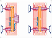
Figure 2: Single face vs. stack mold hot halves.
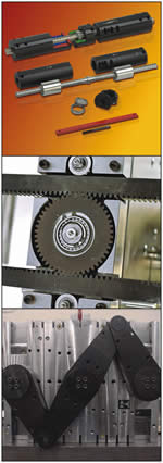
Figure 4: From top to bottom: helical gear centering device components, rack and gear centering device and harmonic arm centering device on the mold. Images courtesy of D-M-E Company. Figure courtesy of Integrity Mold & Die Ltd.
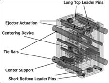
Figure 3: Stack mold design guidelines.
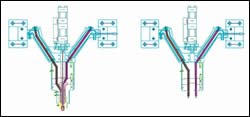
Figure 5: From left to right: machine-based co-injection “Y” manifold, mold-based co-injection “Y” manifold.
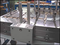
Figure 6: Two-shot manifold hot half viewed from the side injection.
Figure 1: Series and parallel MPL systems. Figures courtesy of D-M-E Company.
Market trends such as the need for increased productivity, shorter leadtimes, lean operation and lower cost parts are driving the popularity of molding technology designed to add efficiencies to the process. This has all led to the increased interest in and use of multi-parting line and multi-material systems.
During injection, two mold halves touch each other at the parting surface, or the parting line. The number of parting lines can be increased if there is a need for higher productivity. Multi-parting line (MPL) systems are gaining popularity as molders look to improve their molding productivity. Stack molds have twice the effective output of single-face molds, but they also require more design, manufacturing and maintenance time.


Multi-parting line systems are classified based on parting line arrangements, the number of barrels in the molding press and the type of functional subassemblies they use to operate safely and economically. This article will address these options. It will also introduce mold design guidelines and show how to select and size some of these subassemblies using a calculation program.
Multi-parting line systems, in series or parallel arrangements, are used instead of single-face molds to:
- increase productivity without increasing floor space (stack molds)
- mold high quality components if the part size is too large for a family mold arrangement, and when requiring absolute color match (stack molds)
- save premium material by using low-value filler material inside the part (co-injection molding)
- increase structural strength by introducing reinforcement inside the part while maintaining aesthetic appearance on the outside (co-injection or overmolding)
- form an integral part of the substrate part and seal material (two-shot or overmolding)
- increase shelf time of PET bottles for carbonated beverages by effectively retaining CO2 inside the bottle and blocking oxygen out (multi-layer)
- save time on setup of the mold and assembly, packaging and sorting of the parts
Often the need for greater productivity leads to MPL use. It can be more economical to have two or more operations done in one press cycle without moving the part from one station to another. Aesthetic, functional and structural requirements also create the need for multi-material systems. The multi-material process can be divided into two major groups:
- Co-injection involves two materials injected simultaneously or in a sequential manner while the mold remains closed. The two materials are usually injected through the same gate and the part does not move between cycles.
- Two-shot or multi-shot molding occurs when the part is mechanically moved between cycles. Overmolding describes a similar process, although it can also refer to the process of plastic molded over a metal insert, such as the handle of a hand tool. The part transfer occurs while the part is still on the core using rotary tables, shuttle action, robots or spin-stack technology. In this process, the two materials are injected through different gates.
Hot Runner Systems
Hot runner systems are almost always used in MPL and multi-material systems. A hot runner system transfers resin from the machine nozzle to the gates at a set temperature within a set time to reduce cycle time and eliminate material waste.
Their main requirement is to find balance between the residence time in the hot runner and pressure loss during injection. Processors lose less pressure using large channel diameters; however, melt residence time increases, creating degradation and/or color change problems.
A typical hot runner system might operate like this:
- A sprue bar, extended sprue bushing or manifold extension nozzle transfers the melt from the machine nozzle to the manifold at an even temperature.
- The manifold then distributes melt to the sprue, hot tip or valve gate nozzles. The flow channel is designed and machined to provide balanced pressure loss and smooth directional turns without any hang-up areas.
- The nozzle’s function is to transfer the melt to the gates. The processing sensitivity of some materials requires a precise heat profile along the length of the nozzle.
Arrangements of Parting Lines in MPL Systems
MPL systems are grouped based on where the parting lines are located relative to each other. They can be in series arrangement or parallel arrangements.
Series Configuration
In a series configuration, the parting lines are located one after the other from the locating ring toward the moving platen.
Plastic is injected into cavities from the center portion requiring only one barrel; however, a series configuration can be used with a multi-barrel press if desired. This configuration also allows the plastic to be injected into the mold halves clamped directly to the platens. The center of the mold forms the core and moves the parts from one side to the other.
Parallel Configuration
In parallel configuration, the parting lines are next to each other if looking from the locating ring to the moving platen. There are always two barrels with this arrangement, either parallel or perpendicular to each other. If perpendicular, it can be an independent, bolt-on unit.
As shown in Figure 1, each MPL system needs one or more of these components for the melt delivery system.
Drool Reducer
Drool occurs when the resident pressure in the manifold and nozzles pushes the melt through the orifice into the atmospheric pressure at the separation point. Drool reducers are used at the end of sprue bars to reduce the drool from the center manifold. Resident pressure pushes the drool reducer out by a predetermined stroke. The drool from the stationary sprue bar or machine nozzle is reduced by suck back (decompression) on the machine side.
Shut Off Valve
Stack molds are used for molding close profiles, so there cannot be any obstruction in the parting line. In this case, the separation point must be at the parting line. There cannot be any drool because accumulation of plastic on the parting line can interfere with the closing of the mold (flashing). This typically means using a machine with an extension nozzle and a shut off valve.
Heat Expansion Compensation Device
When the separation point is not between the machine nozzle and the sprue bar, the length of the sprue bars in closed position is critical. The combined length of two sprue bars needs to be exactly the same as the shut height of the mold or mold portion on the stationary side. If the sprue bar assembly is longer, there is flashing at the stationary parting line, if shorter, there will be leakage at the separation point. A heat expansion device compensates for the temperature-caused length differences in the sprue bar assembly while maintaining the necessary seal-off force at the separation point.
Interface Device
Dimensional differences occur due to temperature differences and inaccuracies in the manufacturing process. If a dual-mold carrier is used or a melt delivery system is designed to accept several single-face molds at the same frame, it is unlikely that the distance of spherical radii from the outside surface of the clamp plate and of the individual mold will be identical. Using an interface device at the transfer point between the carrier frame and the mold compensates for dimensional differences while maintaining necessary seal force.
Stack Molds
Stack molds are the most popular MPL system. They are essentially two, single-face molds back-to-back, fused together by the common manifold. The two parting lines are in series arrangement (see Figure 2).
The biggest advantage of a stack mold is a processor can double output within the same tie bar distance as a single mold. A molder can often also use approximately the same machine tonnage as with a corresponding single-face mold. For certain applications, up to a 15 percent increase in tonnage may be needed.
There are some considerations when using stack molds. Parts must be relatively shallow to work. The initial cost may appear higher, but, in fact, it is lower than the alternative use of two single-face molds. Cycle times increase slightly, but are faster than using two single-face molds for the same amount of output. Stack molds require the molding machine to have more daylight and a larger injection unit. The best applications are high-volume items such as lids, containers or bowls, mating parts, RH and LH parts in the same mold.
Basic design guidelines for a stack mold include:
- keep long top leader pins engaged while mold is open
- ensure short bottom leader pins do not interfere with falling parts
- have support for center portion (this may ride on the tie bars or machine ways)
- use the same ejector actuation on both sides to achieve identical ejection dynamics on both the stationary and moving sides of the mold (see Figure 3).
Plate Control Subassemblies of a Stack Mold
Centering devices are used to make sure that the two parting lines open simultaneously and equally.
The different types are:
Helical gear (a.k.a. spline, multi-start screw, coarse threaded axle)
This is lightweight and adjustable solution. It accommodates robots and is easily reset. The overstroke will not cause any machine damage, and there are built-in safety features. Nylon inserted nuts act as shock absorbers with the large inertia forces of fast cycle times. Its small footprint is ideal for in-mold labeling and side-entry robots. Helical gear (HG) centering devices can be placed (and recessed) at the corners of the mold, leaving the top, bottom and sides fully accessible.
Rack and gear (or rack and pinion)
This is typically the most inexpensive option. But, it is not easily adjustable, it is difficult to use with robots, and the overstroke requires a lengthy repeat setup.
Harmonic arm (linkage)
This option is used when it comes as part of the mold carrier system or the press itself. Harmonic arms are large, not easily adjustable and can be awkward for side entry robots. Overstroke can create serious damage (see Figure 4).
Based on the advantages of helical gear technology, one hot runner and mold component supplier has standardized these devices for the industry, which allows components and mounting dimensions to remain consistent, saving tool designers and toolmakers design, manufacturing and sourcing time.1
The helical gears are available with nominal outside diameters of 28mm or 38mm and the blank, uncut (maximum) lengths range from 1000mm to 1500mm. Lightweight aircraft aluminum housings help with the installation and maintenance process. The nut housing and the helical gear are customized for each application.
There are also some physical limitations on how much parting line opening can be achieved with a certain stack mold shut height. A configuration program has been created to check the requirements and provide the final dimensions for these two components. The output of the calculation gives the two lengths tailored to the particular mold and the required parting line openings.
Center supports are used to keep the center portion aligned while the mold is open and to transfer its weight to the tie bars or machine ways. The assembly should be height adjustable to compensate for wear. Newer developments in this area eliminate sliding surfaces and replace them with rolling action. The minimal wear and precise alignment achieved by a more elaborate design result in a relatively more expensive device.
Multi-Material Systems
Multi-material applications have been used in the automotive industry for years, often to eliminate complex assembly procedures. For example, it is not unusual for a car lens assembly to be molded using four injection units. Multi-material molding is also useful when the texture of a part is important.
Multi-material parts can be molded two ways as previously discussed, using co-injection or the multi-shot process. Molds that utilize a multi-material process almost exclusively use hot runners. The hot runners may have separate manifolds for each color or independent flow channel paths for different colors in the same manifold.
Co-Injection Molds2
This process creates a skin and core material arrangement in a molded part. The skin material is injected first into the mold cavity and is immediately followed by injection of the core material. As the skin material flows into the cavity, the material next to the cavity walls freezes and material flows down a center channel. When the core material enters, it displaces the skin material in the center of the channel by pushing the skin ahead. As it flows ahead, it continues to freeze on the walls, producing the skin layer.
Machine-based Co-Injection
The co-injection process requires two injection/processing units. The units generally inject material through a manifold at the end of the injection barrels. The manifold directs the two melt streams into a centrally located nozzle. The machine controls the injection units to achieve a skin-core-skin flow sequence through the manifold into the mold. Lastly, skin flow is needed to clear the short nozzle section of core material and to seal the gate area with skin. This arrangement can be used on any single- or multiple-cavity, conventional cold runner mold.
Mold-based Co-Injection
This same process can be achieved on a hot runner mold by utilizing a special hot runner system. The sequencing process is achieved by a three-stage valve gate assembly at each gate, and it utilizes two injection units. The two melt streams are directed into the mold via separate channels. These two channels remain separate until they reach the gate area of the part. At this point they flow through a nozzle arrangement similar to the co-injection manifold (see Figure 5).
Benefits of co-injection include lower cost parts, higher strength and sound absorption core, reduced cooling time, improved part aesthetics and combined property characteristics.
Applications for co-injection include:
- Foamed core for reduced weight and noise transmission
- Glass-filled cores for improved physical properties
- Low-cost core for cost savings
- High-gloss skin material over structural core material for combination of aesthetic and structural properties
- Post-consumer-recycled material in core (environmental friendly)
- Post-industrial-recycled material in core
- Reground painted parts recycled into core
Two-Shot Molds
Two-shot molds are two independent hot runner systems in the same mold. These two systems can be built in the same hot half in the case of a single-face mold or in different sides of a stack mold such as the spin-stack system. The two injection units can either be part of the injection press, or the second unit can bolt onto the side or top of the mold. If any of the injection units injects into a mold half that moves away from the machine nozzle when the mold is open, a shut off valve is necessary to prevent drooling and save valuable material (see Figure 6).
Summary
Benefits of two-shot, multi-shot and overmolding include clearer brand identification, improved aesthetics, improved combined property characteristics (mechanical, sound reduction, heat insulation, shock absorption) and soft touch requirements.
References
1 D-M-E Company (www.dme.net) has standardized helical gear technology devices for the industry, which allows components and mounting dimensions to remain consistent.
2 The co-injection molding section is based on an article from Milacron called “Co-Injection Molding” by Mark Elsass.


Related Content

The Ins and Outs of Hot Runner Temperature Control
A training checklist that explains the why and how of proper hot runner temperature control and system management.
Read More
Hot Runner Truths, Myths and Overlooked Areas
Addressing hot runner benefits, improvements and everyday issues from the perspective of decades of experience with probably every brand on the market.
Read More
Advancing the Mold With New Technologies
This roundup is full of products and services that help answer concerns and meet needs for the industry. Featured in this roundup are hot runners, mold components, mold materials and more.
Read More
Revisiting Some Hot Runner Fundamentals
What exactly does a hot runner do? If you’ve been in the injection molding industry for any length of time, you might think the answer is obvious, but it is not.
Read MoreRead Next

High Cavitation Molds Promote Economies of Scale
Toolmakers are developing increasingly complex molds for high production of thinwall parts.
Read More
Advances in Hot Runner Systems Drive Innovations in Part Engineering and Styling
Design and performance capabilities of components fabricated in state-of-the-art molds enhance the appeal of new vehicles.
Read More
How to Use Continuing Education to Remain Competitive in Moldmaking
Continued training helps moldmakers make tooling decisions and properly use the latest cutting tool to efficiently machine high-quality molds.
Read More