
Mold Side-Actions: How, Why and When They Work
Understanding the effects of injection on the core, slide and associated components is critical to selecting the best side-action methods for a given application. This first of two articles will discuss the basic physics underlying all side-actions.


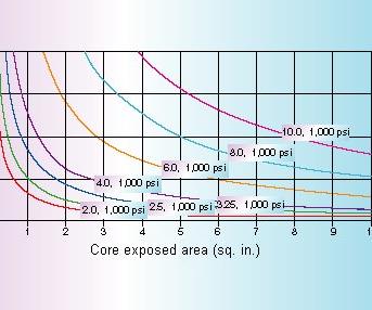
Figure 5: Minimum bore diameter (inches) and hydraulic pressure (psi).
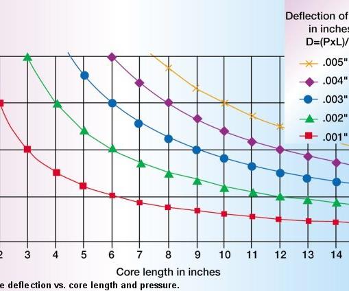
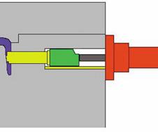
Figure 4: Cylinder only - no backup with full pressure.
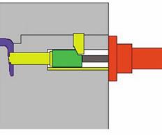
Figure 3: Cylinder with heel block with backup.
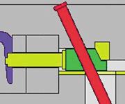
Figure 1: Cam pin action with backup.
As advances in technology have driven market globalization and shortened product life cycles, mold design and production methods have been pressured to keep pace. The success of moldmakers in the future will be defined by their ability to discern the advantages and disadvantages of the ever-broadening options.
With a fundamental understanding of these various side-action methods, moldmakers can choose and apply the optimal solutions to today's applications. Solutions must benefit all of the players involved in the process - designers, moldmakers, molders and product manufacturers. With demands for improved quality, lower costs, shorter production times and increased part complexity, the need for a deeper understanding by all participants is becoming paramount. The need to think "outside of the box" and embrace advanced techniques has never been clearer.


Perfect Fit Actions - Cam Pin Method
The most basic and familiar of all side-actions employs an angled pin to move the core with heel block backup during injection. In the "ideal" mold, the components form a perfect fit when the mold is closed, with the desire that the components do not move or change shape during injection (see Figure 1). The cam pin method, however, has a fundamental limitation in that steel is compressible and flexible.
Because the load forces in a tool during injection can be very large relative to the modulus of steel, assumptions of rigidity and incompressibility are not appropriate. Even with a "perfect fit," during injection, plastic pressure is applied to the core face and the metal is flexed, side loaded or compressed toward the heel block, resulting in slide face backup. The degree of the side loading, flex and compression will determine the resulting flash and other issues.
The magnitude of these problems is a function of the variation in injection pressure and core/mold geometry. Location of stops, size of stops, guides, core length, shutoff area, etc. will all affect the amount of these errors. To understand how the compressible nature of steel impacts the cam pin method, the engineering relationships of stress and strain on cores must be reviewed.
Compression Ruins the Fit
Engineering calculations for materials often focus on yield strength, with little attention to change in shape. Because injection forces are relatively high and small deviations in materials leads to poor part quality, attention to how steel changes shape under load is critical to good mold design. While the mold is machined, assembled and spotted cold, it would be more correct to manufacture the steel components at operating temperature and under the anticipated injection forces.
In mold applications, the known factors are often the injection pressure (P), core area exposed to plastic (C), length of core (L), the major diameter area of core (A), and material property modulus (E). What is unknown is the amount of deflection (D) of the core face. To calculate the deflection for a given force, the "FLEA" formula can be used.
F = P x C
D = (F x L)/(E x A)
Example:
Given a 10" long core pin with a 1.125" diameter major diameter (area of 1"}), a core face exposed to plastic of .5"} and an injection pressure of 10,000 lbs./in.}, the parameters are:
P = 10,000 lbs./in.}
C = .5"}
F = P x C = 5,000 lbs.
L = 10"
E = 30,000,000 lbs./in.}
A = 1"2
D = FL/EA = .0017"
As can be seen, a moderate size core area of .5" (half the pin area) can move nearly .002" under a moderate injection pressure of 10,000 psi. Note that this corresponds to a machine hydraulic line pressure of approximately 1,000 psi1 x 10 for the screw/barrel. For face area equal to the pin diameter (1"}), deflection would be approximately .004" due to pin compression alone. Changing material to a glass-filled nylon could double injection pressure to 20,000 psi, resulting in .008" movement.
Additional factors - such as flex, thermal shrinkage and timing - must be added to compression to determine overall deviation from the desired shape. Of course there are many other concerns for the components themselves. A short, yet informative, description of slide design and other issues can be found in section 12.9.2.1 of Menges and Mohren's How to Make Injection Molds}. Discussions of forces on the pin, most favored angles, wear on heel blocks, recommended slide tapers, concern for thermal effects and delayed lifter designs are included.
A Simple Chart
A simplification assumes constant core cross sectional area, core exposed area equals core slide cross-section area and constant material modulus. Thus a plot can be made of deflections for various pressures and length (see Figure 2).
Close inspection of the data below 20,000 psi shows that all cores greater than 3" in length have at least a .001" compression (core deflection). For greater pressures approaching 20,000 psi, any core length will result in some compression beyond .001".
Thus it has been demonstrated that for the limiting case where the core cross sectional area approaches exposed area, generally all captured cores with perfect size-on-size timing will demonstrate at least .001" deflection or backup of the core face during injection. In most cases, for common core lengths between 6" to 10" and injection pressures of 10,000 to 15,000 psi (1,000 to 1,500 hydraulic line pressure), the deflection during injection will be from .002" to .005". Note that this "movement" is strictly due to compression alone and must be added to the core movement due to flex, timing error, mismatches and thermal contraction.
Without getting involved in estimates of cost or timesavings of various methods, the traditional cam pin system can usually be described as providing the following operational and performance advantages in production:
- It is intrinsic to the mold itself - requiring no external setup, hookups or adjustments by mold setup personnel or operators.
- It has unlimited speed.
While not appropriate for a variety of complex applications - which can be listed as disadvantages relative to other methods to be discussed in Part II - a few disadvantages are:
- It is complex to manufacture.
- It has a one-off design.
- Flash or inconsistent parts occur due to compression under load.
A note should be made here regarding the use of hydraulic cylinders with heel blocks (see Figure 3). While the use of standard hydraulic cylinders can improve or help solve other problems with cam pin actions, they react in the same manner as a cam pin system during injection. Core compression is a function of the length of the core to the heel block and is the same for any method using a heel block. The cylinder simply replaces the pin as another means to move the core in and out when the mold is open.
Compression Fit Actions - Cylinder Only Method
Using the hydraulic cylinder to position the core - with the heel block to hold it - and using it to both position and hold the core are two completely different applications. In the cylinder only method, while the core may have to be set prior to closing the mold due to a design issue, most often it is set and pulled with the mold closed (see Figure 4). During injection, full hydraulic pressure is maintained on the cores to prevent movement.
While full hydraulic pressure during injection is not commonly available - and using standard hydraulic cylinders to move, hold and compress the cores during injection is not normally a viable option - the physics of operation and the advantages provided by such a method are instructive to other methods discussed later. There may be special circumstances where use of this method, despite its drawbacks, provides the best choice for the application.
Compression Is the Fit
A hydraulic cylinder is used to hold the core during injection by ensuring that the force from the cylinder rod exceeds the force on the slide due to plastic pressure. To determine the expected force on the slide (F), the known factors of maximum injection pressure (P) and core area exposed to plastic (C) are used.
F = P x C
The cylinder force must exceed the slide force to prevent movement of the core face. The force from a standard cylinder (M) is a function of the piston area - based on bore diameter (B) in inches - and supplied hydraulic pressure (H) in psi.
M = H x (3.14 x B2)/4
Using the same data from the cam pin example, force on the core is:
P = 10,000 lbs./in.}
C = .5"}
F = P x C = 5,000 lbs.
Given an available hydraulic pressure of 2,000 psi and a 2" bore cylinder, the force available from the cylinder is:
M = 2,000 x (3.14 x 2 x 2)/4 = 6,280 lbs.
Note that if the available hydraulic pressure was only half - or 1,000 psi - the force available from the cylinder would be:
M = 1,000 x (3.14 x 2 x 2)/4 = 3,140 lbs.
In the first case, the force of the cylinder is greater than the force of the plastic and the core face will not move. In the second case, the plastic force exceeds the cylinder force and the core will move substantially until the shot volume is expended. This illustrates the problem of hydraulic pressure dropping out or decreasing during plastic injection. Without hydraulic pressure, the cylinder force is zero.
If the above formulae are set equal and solved for bore size, the minimum cylinder bore diameter can be determined. At the minimum bore size, M = F.
B = SQRT[(4 x P x C)/(H x 3.14)]
Figure 5 shows the minimum bore size needed for various exposed areas and injection pressures at 1,000 psi hydraulic on the cylinder. Before using this method, verify that full hydraulic pressure is available during injection and then verify it again. Even if you are lucky enough to have full injection pressure available, note that it doesn't take much core area (about one square inch) to require a 4" bore cylinder at a minimum. A three-square-inch area gets you quickly to a 6" bore. For a detailed discussion of the relationship between press line injection pressure and actual nozzle injection pressure, review Menges and Morhen}.
For example, with an injection line pressure of 1,500 psi, converted to injection pressure of 15,000 psi, and a core area of four square inches, the point lies above the 8.0, 1,000 psi line and below the 10.0, 1,000 line. Thus at 1,000 psi cylinder pressure, a cylinder larger than an 8" diameter bore would be needed. Since a 10" bore is above the point, it would meet the requirements. Alternatively, use the formula and find the closest larger bore size available.
No Core Movement
The cylinder-only application is noteworthy in that the core is still compressed under load, but the compression is done by the cylinder toward the core face prior to injection. Compression toward the core face is very important.
During injection, the core undergoes load sharing with the core stops, but does not move. Zero movement is preferred to compression of the core against the heel block by the plastic force during injection, as seen previously. Hence, for the cylinder-only method, compression against the stop provides a solution "better than a perfect fit."
It is critical to emphasize that this only works with a hydraulic cylinder when the cylinder is:
- Sized large enough to exceed the force of injection.
- Maintained with full system hydraulic pressure during ejection (not common).
- Is not used with a heel block or other core blocking mechanism.
- Is used with stops on the core very near or at the core face to define core position.
While every application must be reviewed with an understanding of how some particularly strange feature may impact this method, in nearly every practical application the use of a hydraulic cylinder in the manner discussed will provide a wealth of advantages over a cam pin system. Of course, there are a few major problems with the implementation of this method, which will be addressed by the modular core compression side-action system (discussed in Part II).
While modular systems can - in some cases - greatly improve on these traditional methods, there are important lessons to be learned up to this point. When building or employing side-actions of any type, you should observe the following:
- Make the core body as short as possible to minimize "core length" (L).
- Place stops on the core as close to the part as possible to minimize length of core at diameter (L).
- Make core bodies large in cross sectional area even if the face detail is small to maximize (A).
- Design molds to operate at the lowest injection pressure possible to reduce core "force" (F).
- Use a hydraulic cylinder only when possible on small cores with sufficient hydraulic pressure.
REFERENCES
1Johannaber, Friedrich. Injection Molding Machines: A Users Guide, trans. Rolf J. Kahl, 3rd ed., Munich; Vienna; New York: Hanser, Hanser/Gardner, 1994.
2Menges, Georg, and Mohren, Paul. How to Make Injection Molds, trans. Rolf J. Kahl, 2nd ed., Munich; Vienna; New York; Bacelona: Hanser, 1993.
In Part II, the various modular systems (modular mold base systems, modular cam pin systems, locking/braking/clamping cylinder systems and core compression side-action systems) will be categorized to type of method employed (perfect fit or compression fit) and the various advantages and disadvantages of all systems will be discussed.


Related Content

6 Ways to Optimize High-Feed Milling
High-feed milling can significantly outweigh potential reliability challenges. Consider these six strategies in order to make high-feed milling successful for your business.
Read More
Solving Mold Alignment Problems with the Right Alignment Lock
Correct alignment lock selection can reduce maintenance costs and molding downtime, as well as increase part quality over the mold’s entire life.
Read More
Treatment and Disposal of Used Metalworking Fluids
With greater emphasis on fluid longevity and fluid recycling, it is important to remember that water-based metalworking fluids are “consumable” and have a finite life.
Read More
How to Eliminate Chatter
Here are techniques commonly used to combat chatter and guidelines to establish a foundation for optimizing the moldmaking process.
Read MoreRead Next

Mold Side-Actions: Applications Rule the Action
With a firm understanding of the effects of injection on the core, slide and associated components, this second of two articles will discuss emerging modular technologies which provide alternatives to the limited solutions previously available.
Read More
The Advantages of New Modular Tech: Maximizing ROI and Minimizing Risk
Proven off-the-shelf modular mold components and complete component systems meet today’s demanding drive for a lean approach.
Read More
How to Use Continuing Education to Remain Competitive in Moldmaking
Continued training helps moldmakers make tooling decisions and properly use the latest cutting tool to efficiently machine high-quality molds.
Read More