Mold Side-Actions: Applications Rule the Action
With a firm understanding of the effects of injection on the core, slide and associated components, this second of two articles will discuss emerging modular technologies which provide alternatives to the limited solutions previously available.


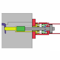
Figure 9: Locking cylinder.
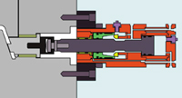
Figure 10: Modular core compression side-action system.
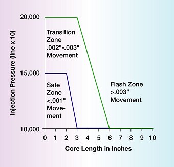
Figure 11: Perfect fit/backup zone.
In the first article, Mold Side-Actions: How, Why and When They Work (see MoldMaking Technology magazine, September 2001), the discussions left two possible side-action systems. The first type is the "perfect fit" action or "backup" action, which comprises all actions that attempt to hold the core position by making components fit exactly. Perfect fit systems:
- React to plastic pressure.
- Compress during injection.
- Compress toward the heel block.
- Have backup of the core face.
- Produce flash easily.
Examples of perfect fit actions discussed were the traditional cam pin method and the cylinder with heel block method. These are methods where the pin or cylinder moves the core and the heel block maintains position during injection.


The second type is the "compression fit" action or "zero movement" action, which comprises all actions that compress the core into position by applying and maintaining a high set force before, during and after injection. Compression fit systems:
- "Pre"-compress against the core stops.
- Share load with plastic and stop during injection.
- Ensure zero movement of the core face.
- Easily prevent flash.
An example of a compression fit action was the traditional cylinder only method. In this method, the cylinder both moves the core and provides compression under full hydraulic pressure before, during and after injection to prevent movement.
Emerging Modular Systems
As with robotics and automation in the last decade, the molding industry is just beginning to embrace the next evolution in mold production - modularity. As important as part quality and mold performance is to the industry, it no longer overshadows price, speed to market, ROI, lifetime cost, competitiveness, etc., which are ever more commonly reviewed and taken into account in today's global marketplace. A large amount of effort has been expended by innovative companies to provide the industry with more cost-effective methods for producing, maintaining and controlling molds, including more advanced CNC equipment, analysis software, CAD/CAM integration and modular mold components. Perhaps the most familiar modular systems are complete mold bases, hot runner systems, quick-change systems, quick connections and modular wiring harnesses. While slide components such as wear plates, pins and other items have been commonly available as off-the-shelf components, it has only been recently that complete modular side-action systems have become widely known.
Often identical to common one-off designs, the more simple components focus their advantages on reducing production time, simplifying mold production, providing standardization and most of all, allowing the moldmaker to take advantage of volume production for low volume usage. For example, making core pins one at a time requires extensive handling and labor (i.e., money), compared to purchasing pins made in large volumes by a component supplier. The component supplier makes a profit and the cost to the moldmaker is often significantly less than the cost to produce the same part. This is modular efficiency on a basic level.
Complete hot runner systems, analysis software, quick-change tooling and the like provide similar modular efficiency by providing systems not only expensive to produce in low volumes by the moldmaker, but which also would require extensive R&D - well beyond the efforts of basic component design. In these cases, the benefits are not defined by cost savings as compared to raw materials or direct machining labor, but in advantages provided by less direct but perhaps more important savings such as improved part quality, consistent part quality, reduced cycle times, increased production efficiency, lower production overhead and lower cost per part.
In some cases the new technology provides a completely new method previously unavailable or entirely cost prohibitive prior to its development. The modular systems that follow are part of this new technology. Not only are the systems important, but it also is equally important to know when to use them.
Modular Mold Base and Cam Pin Systems
Modular mold base systems are basically a built-in side action in the mold base when purchased. The systems are part of a complete modular mold base design. This is indeed a traditional cam pin and mold design without the issues of building one from scratch. Selection is done by choosing the made-to-order or off-the-shelf mold base with installed pins, slides, cores, etc. ready for modification by the moldmaker. Modular cam pin systems limit modularity to the action itself, allowing the mold builder more freedom to place the action in any mold base as desired.
While the modular mold base systems generally emulate the large, traditional cam pin arrangements, the modular cam pin units commonly consist of an angled wedge and integrated angled slide captured in a housing which holds the system together. The device may incorporate a spring-loaded return for small details, automatically retracting the core when the mold is opened. In standard configurations, the drop in system mounts on - or very near - the parting line. When the mold is near full closure, the opposing mold half contacts the plunger/wedge/pin system, driving the core forward to the set position. After injection, the mold is opened and spring force on the plunger pushes the angled arrangement back to the starting position and results in core retraction. Other modular methods provide angled surfaces on manufactured blocks which combine the pin style movements with the heel block attributes and provide similar advantages and operation to traditional systems where the slide is held by a detent and the pin separates from the slide. In any case, these systems provide for simple installation over traditional one-off designs.
While an excellent opportunity and improvement over traditional cams and pins, these modular cam pin systems provide performance consistent with perfect fit/backup actions. Backup will occur as previously discussed for all modular actions employing a perfect fit technique. Use these where you would a traditional cam pin and save yourself some time and headaches.
Modular Wedge/Locking/Braking/ Clamping Cylinder Systems
Similar to the cylinder heel block method, these concepts generally use a cylinder to actuate the slide and a wedging, locking, braking, clamping or other mechanical means to interrupt cylinder rod movement. This is similar to using a cylinder with a heel block, but allows the action to occur totally independent of the mold operation, since the interrupt is internal to the unit itself. With the interrupt or clamp in place, the slide is held in the set position during injection. It is very important to note that the use of a rod interrupt or clamp does not define whether or not the unit will perform as a perfect fit/backup action or a pre-compression/zero movement action.
In almost every case, systems of this type are perfect fit/backup actions. In cases where the rod is held, clamped or blocked in place (like a heel block does without pre-compression), not only is the core compressed toward the heel block during injection, but the cylinder rod also is compressed in the same direction. As in the cam pin discussion, the force on core face during injection causes the slide to compress. Since the heel block is no longer present, the force also compresses the cylinder rod up to the point of clamping, locking, holding or wedging. As these systems often employ an internal means to hold the rod - even in the best case situation - where the clamp is at the rod end of the cylinder, the amount of material compressed is at least a stroke length longer than when using a heel block. Also, the cross section of the rod used is often much less than the cross section of the core body, leading to more compression than would be the case if the diameters were equal. This leads to a total compression of two to four times more than that seen with the cam pin method or cylinder heel block method.
In the case of a locking cylinder (see Figure 9), at the end of the stroke, a groove in the rod accepts locking elements, which are subsequently captured by a cylindrical slide driven by springs.
In addition to the known factors often considered to determine core deflection (D), such as the injection pressure (P), core area exposed to plastic (C), length of core (L), major diameter area of core (A), and material property modulus (E), rod length (available rod + rod stroke = S) and rod cross section area (R) also must be considered.
To calculate deflection of the core face, we use the combined formula previously developed, but calculate deflection for both the core itself and the cylinder rod:
Original formula for slide with heel block:
F= PxC
D=(FxL)/(ExA)
Revised formula for slide with cylinder lock:
F=PxC
D=(FxL)/(ExA) + (FxS)/(ExR)
The original example was:
Given a 10" long core pin with a 1.125" diameter major diameter (area of 1 in.}), a core face exposed to plastic of .5 in.}, and an injection pressure of 10,000 lbs./in.}, the parameters are:
P=10,000 lbs./in.2
C=.5 in.2
F=PxC=5,000 lbs.
L=10 inches
E=30,000,000 lbs./in.2
A=1 in.2
D=FL/EA
D=.0017 in.
Same example with locking cylinder:
As above but add stroke of 5" and a 20 mm rod (.787" diameter). Rod cross sectional area is .5 square inches (R = .5) and S = 5".
F=5,000 lbs. from above
L=10 inches
E=30,000,000 lbs./in.2
A= 1 in.2
R=.5 in.2
S=5in.
D-FL/EA+FS/ER
D=.0017 + .0017 = .00033 in.
As can been seen, a moderate size core area of .5 square inches can move over .003" under a moderate injection pressure of 10,000 psi. This is two times the deflection using the heel block. If the core face is the same as the pin diameter in the above example, the deflection would be approximately .006" due to pin compression alone. Changing material to a glass filled nylon could double injection pressure to 20,000 psi (2,000 hydraulic line pressure), resulting in .016" movement of the core face, not to mention additional factors such as flex and thermal effects.
Note that the locking slide is held in position using springs. The lock face is straight and the springs (sometimes these employ hydraulics) simply provide a means to hold the mechanical elements in place - preventing the rod clamp interface from moving - but do nothing to pre-compress or prevent compression of the rod and slide system.
It is not recommended to use standard locking cylinders or braking cylinders on injection molds. While some manufacturers show and recommend spring locking and clamping systems for use on injection molds, do not use them unless you really understand the issues involved.
Modular Core Compression Side-Action Systems
Most similar to the hydraulic cylinder only method, modular core compression side-action systems comprise any system that contains the means to pre-compress the core prior to, during and after injection; are a single modular unit and do not require interaction with the opposing half of the mold.
While other methods may be developed, the only known systems are confusingly similar to the locking cylinder method. These systems use a cylinder section to hydraulically actuate the slide and a tapered mechanism to compress the core to a very high load. In the case of the modular core compression side-action system shown (see Figure 10), a dual action force intensifier section actuates to apply a very large compressive force to the core. The force on the core is maintained mechanically, once applied, and is independent of the hydraulics once set. Even with complete loss of hydraulic pressure to the unit, the pre-compression force on the core is maintained.
Compression fit/zero movement actions of this special type perform with the advantages of the hydraulic cylinder only method in a more compact footprint and without the need to maintain pressure. After the mold is closed, the cores are set under a large force greater than the force on the core during injection. During injection the core face does not move. After injection, the cores can be retracted prior to mold opening.
The force applied to the core must exceed the injection force to prevent movement of the core face. The force by the intensifier is independent of the hydraulic pressure used to move the core slide and can be as low as 1,500 psi. Once set, hydraulics may be vented or secured to the system. Available output forces are a function of the unit selected and independent of supply pressure. Units are readily available with output forces of 12,000 lbs., 40,000 lbs., 60,000 lbs., 110,000 lbs. and 210,000 lbs.
Using the same example data from previous examples, given a 10" long core pin with a 1.125" diameter major diameter (area of 1 in.}), a core face exposed to plastic of .5 in.}, and an injection pressure of 10,000 lbs./in.}, the force on the core is:
P=10,000 lbs./in.2
C=.5 in.2
F= PxC=5,000 lbs.
Using a core compression side-action system as described, the force available from the intensifier is 12,000 lbs. (M = 12,000 lbs.).
Note that regardless of hydraulic pressure, the force of the side-action system is 12,000 lbs. Note also that this unit has a cylinder bore size of 1.25", much smaller than the 2" bore hydraulic cylinder used in the original example and has an outside diameter of 3". During injection, press hydraulics drop out, but the system maintains full force on the core face. The force of the system is greater than the force of the plastic and the core face has zero movement.
As systems of this nature employ a mechanical pre-compression of the slide, output forces are developed based on mold geometry. As some designs may have aspects that significantly affect assumed compressibility of the core and may exceed the ability for the intensifier to operate, consult the manufacturer for details on sizing, application and use of particular products.
Start With the Application
With a full arsenal of techniques for side action design, we can now discuss how to use them. Begin with the application.
Some questions to consider are: What are my quality requirements? Can I tolerate .005" movement of my cores? Is flash OK? How much? Do I have a seal off? Is this application a medical implant or medical waste container? What is the process? Is the part poly, ABS or glass filled nylon?
Fundamentally, the methods discussed open up a wide range of options. In many cases, designers try to put cores on the parting line, but why? Cam pins. Well, if you can use a modular cam pin submerged in the block or a modular core compression side-action system mounted on a 30 degree angle to the parting line to make the design perfectly simple, why not do it that way?
Quick Start Design Selection
While highly simplified, consider the following question groups and the flavor of their answers. Exact numbers are not as important as getting in the ballpark. After going through them, refine any data that might make a difference in your selection of side-action method, as desired.
Questions of Quality and Size
1. What is the tolerance of my part and any associated detail where a core might be required?
2. What is the expected and what is the worst-case material injection pressure of the tool? Will the customer change material? Will thin walls require increased pressures?
3. Based on the preferred layout, what are the strokes on my cores and what are my core body lengths?
After considering the part tolerances and material, including thin wall sections, you will have a good idea of the injection pressures needed for the mold. With core strokes and some idea of core lengths, you have the necessary data to determine if the less precise cam pin methods will work for these conditions.
Assuming that flash occurs at .002" and that part tolerances require maintaining quality to this level, enter the chart with core lengths and pressures. If in the safe zone, consider using cam pin methods (for now). If in the transition zone, carefully review the application assumptions and risks for a more defined look. If in the flash zone, use a core compression method to ensure proper mold performance. If the part tolerances are not critical and/or some flash is acceptable, cam pin methods would still be a good option for this part of the review, regardless of the chart zone (see Figure 11).
Questions of Operation and Space
4. Do I have any need to move a core(s) with the mold closed? Do I have enough daylight for opening on cores? Do I desire to run in the smallest press possible?
5. Do I have any face seal off areas and/or precision holes or details that must be perfect, even though general part tolerance is not critical?
6. Based on my preferred layout in the base, are my cores on the parting line or off parting line at some angle?
Regardless of the ability to use a cam pin for questions 1, 2 and 3, location relative to the parting line for ease of operation and blocking becomes important to consider.
First of all, do you need or desire for the design to pull the core with the mold closed? Is the core best off the parting line? If yes, consider if the cam pin will work at all, if it can be submerged for the off parting line case or if a core compression system that can be easily mounted at any angle to the parting line is a better choice.
Even on low tolerance parts, seal offs are often used to create holes in the part. Movement of the cores in this case, even if overall part tolerances are not demanding, will often result in holes flashing over. Flashing of holes for any part is usually a problem. With the exception of straight pin holes, all detail cores with small shutoffs have a high propensity for movement and flashover. Such cores should use a core compression/zero movement method to prevent lifting of the seal offs.
Daylight and press size issues become important for long core applications. Modular core compression side-action systems can be mounted external to the mold base, allowing the mold base be much smaller to fit in a smaller press than would be the case with an internally supported cam pin system.
For long cores where part tolerance requirements are loose and the core is close enough to the parting line for heel block access, the cylinder with heel block may be an adequate solution. As long cores are strongly affected by compression, all but the sloppiest parts should employ core compression/zero movement systems.
Questions of Risk
7. What is the risk to my company if the customer is unhappy, the mold must be modified or the material is changed?
Risk may be the largest design concern in some cases. For simply placed and smaller cam pin actions, perhaps tool modifications and changes to get the mold to work would not be overly costly or painful. In some cases, the designer may or may not have planned for such changes, if they would be needed.
For larger cores and more complex molds, the risk of failure is high. Often, problems cannot be corrected without expensive modifications, lost time and great embarrassment. For these cases, it is better to put the design effort in on the front end, cover all of the bases on part quality and ensure that the parts have the best possibility for success on the first shot. As core compression/zero movement systems often prevent many problems and provide other advantages for design simplification such as non-parting line mounting, pulling with the mold closed, smaller mold bases, etc., the small disadvantage of using a core pull circuit and hydraulics is easily justified.
Creative Problem Solving
Even a straightforward approach to side-action applications is easily derailed by the vast number of variables and demands of the mold design. With a clearer understanding of the physics of various side-action techniques and a basic laundry list of items to consider, it is the designer's challenge to think "outside of the box" and approach the complex mold design from all angles.
Smaller mold bases and smaller press sizes make both parts and molds less expensive. Simpler mold layouts make molds less expensive to manufacture and easier to assemble and maintain. Modular systems allow faster mold builds and more competitive bids. These are just a few examples of how mold design may go well beyond part shape and tolerances.
Simplified Recommendations
Based on the overall value of modular methods and giving some tradeoff value to the disadvantages of hydraulic requirements for core compression/zero movement methods, here are the final results.
Use perfect fit/backup cam pin and heel block systems (modular when possible) for:
- Very low tolerance parts, as desired.
- Core areas less than 0.5 square inches.
- Very short stroke cores.
- Small exposed areas and large slide cross-sections.
- Short core lengths of perhaps two to three inches.
In these cases, the risk of problems is minimal and the unlimited speed of operation, simplicity of installation and limited press requirements make this a good choice.
Use compression fit/zero movement cylinder only (requires full hydraulic pressure during injection) or the modular core compression side-action systems previously discussed (where hydraulics are not needed during injection) for:
- All high quality part requirements.
- Core areas greater than 0.5 square inches.
- Long stroke cores.
- Equal exposed core face to body areas.
- Moderate to small slide cross sections.
- Slide lengths greater than 2".
- Off parting line cores.
- Cores angled to the parting line.
- Core movement prior to mold opening.
- Reducing mold base dimensions.
- Reducing daylight requirements.
While requiring a core pull circuit on the molding machine, the advantages of these systems help ensure part quality and mold performance. The use of the modular core compression side-action system discussed provides the following advantages over the cylinder only method:
- Does not need full hydraulic pressure during injection.
- Mechanical - core compression force even if the hydraulic pressure drops to zero.
- Only 1,500 psi set pressure for full performance.
- More compact than hydraulic-only unit due to intensifier.
- Faster cycle times due to very small bore cylinder section.
It is quite common for all of us to use what we find familiar and it is understandable that demands on our time make discovering and learning new things difficult. However, with demand for improved part quality and increased part complexity sweeping the industry, we must take the time to optimize our use of technology and refine our approach to problems by applying more specific solutions to them.
Gone are the days when all side actions were customized pins and blocks. Current customers demand better.
REFERENCES
Johannaber, Friedrich. Injection Molding Machines: A Users Guide, trans. Rolf J. Kahl, 3rd ed., Munich; Vienna; New York: Hanser, Hanser/Gardner, 1994.
Menges, Georg, and Mohren, Paul. How to Make Injection Molds, trans. Rolf J. Kahl, 2nd ed., Munich; Vienna; New York; Barcelona: Hanser, 1993.


Related Content

Machining Center Spindles: What You Need to Know
Why and how to research spindle technology before purchasing a machining center.
Read More
The Benefits of Hand Scraping
Accuracy and flatness are two benefits of hand scraping that help improve machine loop stiffness, workpiece surface finish and component geometry.
Read More
Advantages and Disadvantages of Copper and Graphite Electrodes
Both copper and graphite provide approximately the same end result, so it is important for a shop to consider the advantages and disadvantages of each material in order to discover what would work best in their shop floor environment.
Read More
Maintaining a Wire EDM Machine
To achieve the ultimate capability and level of productivity from your wire EDM on a consistent, repeatable and reliable basis, regular maintenance is a required task.
Read MoreRead Next

Mold Side-Actions: How, Why and When They Work
Understanding the effects of injection on the core, slide and associated components is critical to selecting the best side-action methods for a given application. This first of two articles will discuss the basic physics underlying all side-actions.
Read More
How to Use Strategic Planning Tools, Data to Manage the Human Side of Business
Q&A with Marion Wells, MMT EAB member and founder of Human Asset Management.
Read More
How to Use Continuing Education to Remain Competitive in Moldmaking
Continued training helps moldmakers make tooling decisions and properly use the latest cutting tool to efficiently machine high-quality molds.
Read More