
Mold Design Tips for Automation
Automation suppliers can assist mold manufacturers with proper mold design and engineering before cutting steel for new molds. Hot runner molds, cold runner molds, box filling, insert molding, stack molds and multi-component molding are areas that can be built and managed more inexpensively, reliably and simpler.


Insert molding. Images courtesy of Wittmann, Inc.
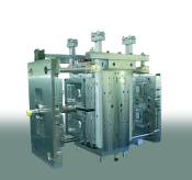
Stack mold.
Automation work cells such as insert molding, box filling and in mold labeling/decorating can all be built with greater reliability and simplicity for a lot less money with proper mold design. Even simple automation—such as sprue removal or pick-and-place—can benefit from early discussion about the requirements between the toolmaker and automation supplier.


Hot or Cold Runners
Molds with hot runner or valve gate systems will simplify end-of-arm-tooling (EOAT) design and reduce cost by eliminating runner grippers or vacuum cups and allow for faster part removal. If a mold must have a cold runner, try to sub-gate the parts from the runner and have round pads for vacuum removal, this will eliminate the need for a post mold degating device and save cycle time for other operations. Vacuum runner removal is faster, lighter and less expensive when compared to pneumatic grippers.
When the mold cannot have sub-gated parts a degating station will be needed. A degating station can be as simple as a pneumatic nipper mounted on the robot traverse beam to a sophisticated floor-mounted station with guillotine style shears to cut long fan gates. A simple degating station with two to four nippers can cost as little as $5,000 to $7,000.
Try to keep the gates accessible when designing for scissor-like cutters. Do not have curls in the runner or have runner branches close to the part obstructing the nipper blades.
Box Filling
Mold cavity layout and quantity can be designed to allow easier robotic box or fixture loading. If the shipping container or fixture is defined, design the mold with an even increment of that container. For example, a box holds 40 parts, design the mold with 10, 20, 40, 80 cavities. Forty-eight cavities doesn’t work, a queue station and an external accumulating device will be required adding, cost and complexity along with using additional valuable floor space. Cavity layout also will help with loading a box with parts. Design the mold with part orientation in mind for pack-out.
A boxing conveyor can be used to pack parts unattended from 30 minutes to eight hours. Empty boxes are moved to a loading area, clamped and robotically filled. Then full boxes roll out past the safety guarding and accumulate on a gravity roller conveyor.
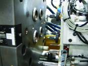
Insert Molding
Insert loading is an easy process if the mold is designed properly. Try to keep the insert and removal sides of the mold opposite. Insert on the mold “A” half and part removal on the “B” half. This limits the mold open time, but requires more mold open dimension. Have generous lead-ins for the inserts, and avoid having any obstructions in the path of the end-of-arm-tooling (leader and horn pins).
If possible have the inserts positively located in the mold with little interference. Press fit of inserts will require mold docking and clamping to allow thrust cylinders to push the inserts into the mold. Magnets or a vacuum should be used to hold flat inserts on the mold face.
Mold and insert end-of-arm-tooling docking may be required for very accurate insert placement. The mold simply will have female taperlock style end-of-arm-tooling locators mounted in the insert side of the mold. The use of female taperlocks eliminates the need for clearance pockets in the opposite mold half. These taperlocks should be located close to the part cavity. This gives the end-of-arm-tooling a lot of stability, accuracy and keeps the overall size smaller.
Inserts can be presented to the robot end-of-arm-tooling by a simple manual shuttle drawer with fixtures for a single shot worth of inserts to a vibratory feed system with escapements and staging for an extended unattended runtime. The choice of system depends on how much investment makes sense: the difference could be as much as $100,000 to upgrade from the manual drawer to the unattended runtime solution. However, running three shifts seven days a week could justify this upgrade.
Design the mold to allow for a missing insert(s). Filling an open insert cavity during molding shouldn’t damage or require the cavity to be cleaned out to get back into a production run.
Stack Mold Design
Parts are removed either from the top or side of the mold (usually determined by cycle time). Be aware of mold obstructions—such as stack mold linkages, hot runner control cables and connectors, cooling hoses, etc., which could interfere with the take out robots end-of-arm-tooling. Also keep the cavities inside the tie-bar and leader pins clear of the sprue bar for unobstructed part removal.
Deep parts, like deli containers, should use an air eject system with or without a stripper plate for the fastest removal time.
Mold open stroke also needs close attention. To remove parts with a robot requires more mold open daylight than just eject and drop. The robot mold extraction arm and end-of-arm-tooling must fit in the mold along with the part and core. A molding machine with extended tie-bars may be required to give this open dimension.
Multi-Component Molding
Two, three or four component molding can work with automation just as easy as single component. Two types are manual transfer and rotating molds. Manual transfer requires the robot end-of-arm-tooling to remove the substrate from the first cavity, remove the finished parts from the second cavity and place the substrate into the second cavity (overmold). This type of mold design requires a very large and complicated end-of-arm-tooling, usually a larger robot for payload and extended strokes, and will keep the mold open for approximately 6 seconds—all adding cost and time to a workcell.
The better solution is a rotary table mounted to the moving platen that rotates the mold B half to move the substrate to the overmold position. At this point, the robot can either allow the mold to rotate prior to entering or enter the mold to remove the finished parts, leave the mold and permit the mold to rotate.
This table is either hydraulic or servo activated. In either case, the rotation of this table should be controlled by the robot through the injection molding machine electrical interface. The ejector system needs to be independent for each half of the mold (the substrate and finished part). The robot will permit the finished part ejection while leaving the substrate in place.
A robot can be used if the second or third injection unit is mounted vertically over the fixed platen. The robot is mounted over the clamp end of the injection molding machine on floor stands and either picks parts from the top or the side through the injection molding machine safety gate.
Adding the rotary table may require a larger injection molding machine or extended tie bars to allow for the additional mold open dimension required for the rotary table and robot end-of-arm-tooling.
Summary
Automation suppliers could assist with mold design concepts prior to cutting steel for new molds. Simple details like center-to-center cavity spacing, part orientation and gate locations all can make automating simpler and less costly. The cost of adding a hot runner system or sub-gating runners to a mold can be easily justified by the savings gained from eliminating and/or simplifying downstream equipment.


Related Content

Making Quick and Easy Kaizen Work for Your Shop
Within each person is unlimited creative potential to improve shop operations.
Read More
What You Should Consider When Purchasing Modified P20 Steel
When buying P20 steels that have been modified, moldmakers must be aware of the variations and key issues that affect delivery, cost and lead times.
Read More
How to Correctly Size a Hydraulic Cylinder
This week Randy shares steps for correctly sizing a hydraulic cylinder on a mold.
Read More
The Benefits of Hand Scraping
Accuracy and flatness are two benefits of hand scraping that help improve machine loop stiffness, workpiece surface finish and component geometry.
Read MoreRead Next

Standardize Before You Automate
After standardization, automation will create the largest increase in profits that any one area can produce.
Read More
Are You a Moldmaker Considering 3D Printing? Consider the 3D Printing Workshop at NPE2024
Presentations will cover 3D printing for mold tooling, material innovation, product development, bridge production and full-scale, high-volume additive manufacturing.
Read More
How to Use Strategic Planning Tools, Data to Manage the Human Side of Business
Q&A with Marion Wells, MMT EAB member and founder of Human Asset Management.
Read More