
May the Force Be with You
Unlocking the true potential of magnetic workholding for machining mold bases and inserts lies in understanding clamping and machining forces.
The milling magnet is just the foundation of magnetic workholding. With specific accessories and techniques, mold builders can begin to unlock its hidden potential, including enabling them to take on parts they used to avoid. Images courtesy of Schunk.
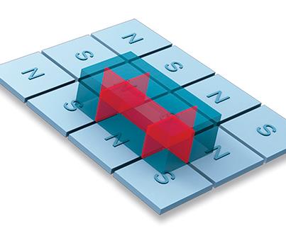
Fig. 1 - A square-pole milling magnet features a grid of north and south poles instead of just two poles on the clamping surface.
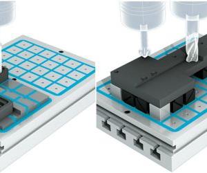
Fig. 2 - Top tooling, such as fixed pole extensions, adjustable pole extensions, pole plates and magnetic parallels, are extensions of the basic magnetic table.
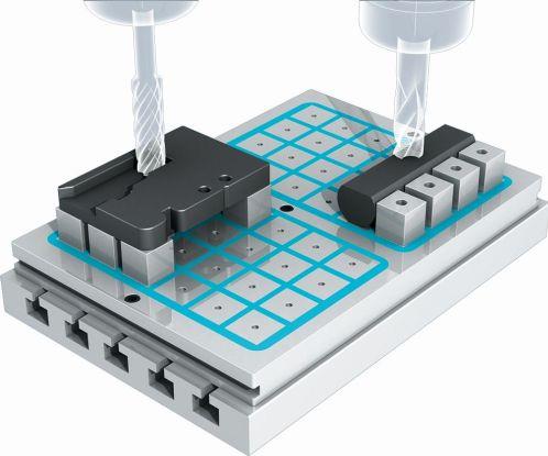
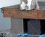
Fig. 3 - Top tooling can create clamping forces on the side of the part, which allows round parts such as this one to be machined on a magnet.


Imagine a large, raw block of steel floating freely in space that requires machining on six sides. How nice would it be if that part rotated so that all six sides could be machined easily? Unfortunately, that part would need to be held in position in some way. Magnetic workholding is one such way. As a matter of fact, it is a proven method used in machining mold bases and inserts, and mold builders have even helped to shape the path for the progression of this technology over the years.
Holding a part with a magnetic milling table is quite simple. Place the block of steel onto the magnet and hit the power button to clamp the workpiece in place. However, by using certain accessories and techniques, mold builders can unlock the hidden further potential of magnetic workholding, including that it can enable them to work with parts they shied away from previously.


Have you ever tried to square up a small part, say 2 by 4 inches, on a magnet and then decided the magnet was not right for the job? By using pole extensions to create side clamping forces and a more free-cutting tool, you may find that the magnet already in place on the machine table is perfectly capable of machining this part without sacrificing the number of setups or metal-removal rate. Let’s take a look at how magnetic workholding technology has evolved and the potential that still needs to be unlocked.
Clamping and Machining Forces
The most fundamental consideration in any workholding solution is that the clamping components can withstand the cutting forces applied to the part. When using a magnet to hold a workpiece, it is important to understand the basics of the technology, including exactly how the magnet is actually holding the part. It is not magic. You can predict and calculate the clamping forces of a magnet. These can then be compared to machining forces and used to determine the proper cutting parameters and setup requirements for machining a particular part. The clamping force created by a magnet is directly proportional to the area in contact and the amount of magnetism flowing into the workpiece. Everything revolves around the workpiece. The application engineer will take into account the geometry, material type, material hardness and surface finish in determining the actual clamping force on a
particular part.
At its core, the workholding (whether it be a magnet, a vise or a specialized fixture) creates clamping forces on the workpiece in order to resist machining forces. For example, almost everyone in manufacturing is familiar with using a vise to hold a part. The jaws of the vise create clamping forces perpendicular to the part surface as the part rests on some form of hard stop (mechanical stop) beneath or on the jaws. It is common practice to take heavier cuts in the direction of the clamping jaws, because milling too far away from the jaws creates a very high lever effect that makes it more difficult to overcome the clamping forces in this direction without either breaking the clamping mechanism or ripping the part out of the vise.
In contrast, it is also possible to machine heavier cuts parallel to the jaws. However, in this situation, the part is held only by the friction created between the jaws and the workpiece. This means the part is more likely to shift inside of the workholding if the machining forces overcome the frictional forces. The same concept of clamping forces versus machining forces can be applied in using a magnet.
When holding a part with a magnet, the clamping forces are created by connecting a series of north and south poles on the surface of the magnet with the part itself. Take, for example, a standard lifting magnet that requires a lever to turn it on and off. On the bottom surface of the lifting magnet are two poles, one north and one south. When a part is attached to the lifting magnet, the part provides a path for the magnetism to flow from the north pole to the south pole. The same is true for a square-pole milling magnet, but instead of having two poles on the clamping surface, there is a grid of north and south poles, as shown in Figure 1.
One of the advantages of clamping a part with a magnet is that the clamping forces are spread uniformly across the surface of the part. This reduces vibration during machining and leads to better part quality and increased cutting tool life. Also, since the part is being held only on one side, the remaining five sides are exposed for machining, which can reduce the number of operations and help achieve tighter tolerances.
When a part is held in this manner, the machining forces are typically acting in a direction that is parallel to the surface of the magnet. This is exactly the same scenario as machining parallel to the jaws of a vise when the part is clamped by friction alone. A good rule of thumb when milling a part held with a magnet is that if the part is 10 by 10 inches or larger, the frictional forces are sufficient to resist the machining forces. If the part is smaller, irregularly shaped or made of a “magnetically poor” material, or if unusually high metal-removal rates are required, then it is beneficial to use accessories and top tooling to aid in the setup. Such top tooling and accessories (standard or custom components) serve as extensions of the basic magnetic table and include fixed pole extensions, adjustable pole extensions, pole plates and magnetic parallels (see Figure 2).
One of the most underutilized strategies of magnetic workholding is the use of side forces, which act in a direction perpendicular to the rest of the magnetic clamping forces. By using poles that make contact with the side of the part, as shown in Figure 3, top tooling creates clamping forces
on that side. This not only works directly against the machining forces, but also allows for the option of milling into the hard stops. This would be equivalent to milling into the jaws of a vise.
Top tooling is not only used to achieve better clamping forces and cutting parameters, but it can also be used to hold a wide variety of parts that are not typically associated with magnetic clamping technology, such as oddly shaped mold inserts, castings, forgings or parts with multiple uneven surfaces. Examples of such applications include using V-blocks or parallel poles to machine round parts; adjustable pole extensions to hold a part that is not flat in its natural position; adjustable pole extensions to aid in achieving flatness and parallelism; special pole extensions to reduce stray magnetism on thin parts; and custom top plates as dedicated magnetic fixtures or for part location.
The milling magnet is just the foundation of magnetic workholding. Using top tooling and accessories wisely unlocks its true potential.


Related Content

Machining Center Spindles: What You Need to Know
Why and how to research spindle technology before purchasing a machining center.
Read More
6 Ways to Optimize High-Feed Milling
High-feed milling can significantly outweigh potential reliability challenges. Consider these six strategies in order to make high-feed milling successful for your business.
Read More
The Benefits of Hand Scraping
Accuracy and flatness are two benefits of hand scraping that help improve machine loop stiffness, workpiece surface finish and component geometry.
Read More
Maintaining a Wire EDM Machine
To achieve the ultimate capability and level of productivity from your wire EDM on a consistent, repeatable and reliable basis, regular maintenance is a required task.
Read MoreRead Next

Are You a Moldmaker Considering 3D Printing? Consider the 3D Printing Workshop at NPE2024
Presentations will cover 3D printing for mold tooling, material innovation, product development, bridge production and full-scale, high-volume additive manufacturing.
Read More
How to Use Strategic Planning Tools, Data to Manage the Human Side of Business
Q&A with Marion Wells, MMT EAB member and founder of Human Asset Management.
Read More
Reasons to Use Fiber Lasers for Mold Cleaning
Fiber lasers offer a simplicity, speed, control and portability, minimizing mold cleaning risks.
Read More