
Machining Complex Contours
Advanced, integrated processor geometry eases processing and predicting of turn-mill contour operations and residual grinding stock allowance.
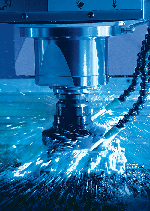
Intelligent kinematic transformation is how the CNC maintains proper orientation of the cutting path, even in a mold’s deep pockets and on its contoured surfaces. Images courtesy of Siemens Industry.
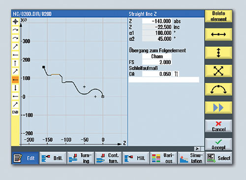
This partially defined turned contour element can be automatically calculated and executed (including allowance for residual grinding stock) with an integrated processor geometry on a CNC.
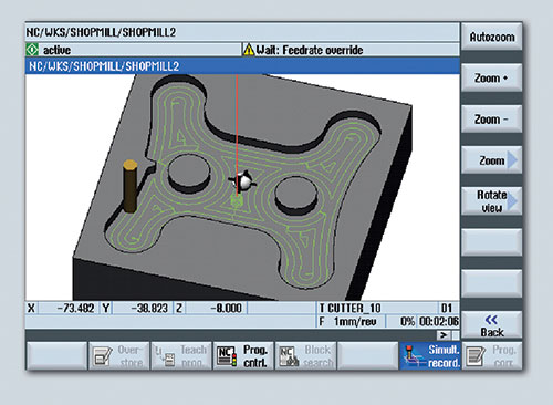
An advanced CNC’s contour calculator enables all face-cutting and plunge-turning tools used for this milled contour pocket to be programmed with less effort and high reliability.


The technical term is “intelligent kinematic transformation,” but all it really means is that today’s CNC should be able to maintain the proper orientation of the cutting path, even in a mold’s deep pockets and on its contoured surfaces. This applies whether milling a mold surface in a rotated plane, or turning the front face or peripheral surface of a turned insert.
If you’ve become attached to your pocket calculator, or to sophisticated and expensive CAD/CAM post-processor programs, you can still keep them, but they might soon become as obsolete as that appliance repairman from the old television commercials. Here’s why:


The advanced integrated processor geometry of today’s sophisticated CNC allows the assignment of specific position patterns such as lines, circles or grids for milling and drilling cycles with just a few inputs from the keyboard. It’s actually the algorithm scale that enables the look-ahead feature and contour smoothing of the high-end CNC, based on NURBS (non-uniform rational B-spline) technology. The kinematic transformations in the CNC enable these position patterns to be called up without any calculation or other programming steps, even on inclined workpiece surfaces in milling, or the end faces and peripheral surfaces of turned parts.
Kinematic transformations are made by the CNC to speed up or slow down the cutting path and adjust the tooltip based on the orientation of the workpiece and the anticipated changes in direction needed to cut a contour or pocket most effectively. It’s basically the control’s ability to orient the cutting path to the position of the workpiece in space versus to the position of the tooltip. The control can take a 3D scan of the workpiece in real time and maintain the proper orientation of the tooltip to affect the proper cutting path. This is especially useful on very large, contoured mold paths.
Cycle geometries for standard operations such as turning shoulders, thread undercuts and trapezoidal grooves can be assigned in a similar way. Since these turning cycles can be used in all workpiece quadrants, even the machining of inside contours becomes simpler and more predictable. And all of these cycles can be applied to a counter spindle without any restrictions, because the programming can be automatically recalculated by the control without requiring a new program.
Hold on though, it gets better.
These cycles are not limited, by any means, to creating standard geometries. They can be used to produce any type of contour or pocket with islands, even with rotating tools on machines. What applies to the milling contours can also be done with rotating turn tools by using a recently developed contour stock removal cycle. Given a defined pocket, sidewall or contour, the stock removal process can be executed in a faster, more efficient manner, prior to slowdown of the machine for first and finish passes. This type of cycle facilitates not only the typical longitudinal and face-cutting operations, but also contour machining with recess or plunge-turning tools.
Complex contours can be generated on the more sophisticated CNC because of this processor geometry, and partially defined contour elements are calculated automatically. Rather than a new cutting path being generated in code, the CNC stores a series of program steps and allows a simple cut-and-paste action when building the program for a multi-cavity but identical mold pattern.
In addition, a simplified CAD reader can be installed onto a PC to convert DFX files into the proper geometric language for the CNC. The part program is built up for the mold with automatic step-and-repeat functions that allow considerable reduction in programming time when all the cavities have the same shape, although different orientation, to the cutter path.
Lastly, sophisticated CNCs enable cutting on a swiveling a plane, whereby the desired coordinate rotation is programmed and the CNC automatically orients the machining to the proper position. This function can also apply to a counterspindle, whether it’s being used to support the workpiece or machine its backside. A good numerical control can automatically handle spindle synchronization, gripping, pulling and even parting of the workpiece. The means the control has the power to interpolate the various axes of motion to perform all the these actions, plus has the memory and repeatability to recognize the position of the workpiece in relation to the cutting tool. In the most advanced versions, onscreen simulation will allow a cutting cycle to be displayed in 3D, real-time and actual cutting conditions, although this can (and should) also be completed offline. Doing so ensures better production runs, and allows for better scheduling and even better estimating of job costs and raw material needs.
This straightforward counterspindle cycle enables operations to be accomplished without any additional CNC language commands and sloping surfaces to be programmed easily. The machining plane can be rotated to the correct orientation without the need for either that trusty pocket calculator or CAD/CAM system preparation.
On older or less powerful CNC models, code is needed for each plane of motion, even when the shape of the cavity is identical. Newer CNC technology enables that code to be automatically stored in the CNC memory and be replicated and re-oriented to another plane of motion. The upside is a considerable savings in time with no loss of part integrity.
In the end, machining molds with complex inside contours with relief cuts or deep pockets becomes much easier on a machine with a more sophisticated CNC. A geometric tracking function can even handle the identification of residual material automatically.


Related Content


The Trifecta of Competitive Toolmaking
Process, technology and people form the foundations of the business philosophy in place at Eifel Mold & Engineering.
Read More
3D Printing Enables Better Coolant Delivery in Milling Operations
Just like 3D printing enabled conformal cooling channels in molds, additive manufacturing is now being used to optimize coolant delivery in cutting tools.
Read More
The In's and Out's of Ballbar Calibration
This machine tool diagnostic device allows the detection of errors noticeable only while machine tools are in motion.
Read MoreRead Next

How to Use Strategic Planning Tools, Data to Manage the Human Side of Business
Q&A with Marion Wells, MMT EAB member and founder of Human Asset Management.
Read More
How to Use Continuing Education to Remain Competitive in Moldmaking
Continued training helps moldmakers make tooling decisions and properly use the latest cutting tool to efficiently machine high-quality molds.
Read More
Reasons to Use Fiber Lasers for Mold Cleaning
Fiber lasers offer a simplicity, speed, control and portability, minimizing mold cleaning risks.
Read More