
Knowledge-Based CAD/CAM: Separating the Hype from True Machining Intelligence
CAD/CAM systems that incorporate knowledge-based machining increase moldmaking efficiency by requiring less time to program parts.


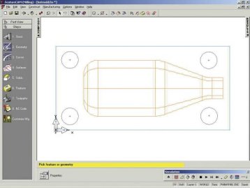
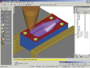
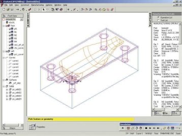
These three images illustrate the process of moving from geometry to features to simulation with NC code generated.
A 2-D solid model that was imported and programmed with automatic feature recognition-automatically recognizing all the features in the part.
More and more CAM software developers are moving in the direction of knowledge-based machining (KBM). KBM is when machining intelligence is built right into the CAM software. KBM is used at various levels and degrees in different CAM systems.
In today's hard-driving push to make parts faster and cheaper, these CAM systems offer push-button automation while retaining control over the machining process.


With machining intelligence built right into the program, CAM systems that incorporate KBM increase efficiency by requiring less time to program parts and producing more consistent NC codes. The latest CNC machines already are automated, so programming should be as well. In addition, KBM should provide expanded capabilities to help manufacturers use more cost-effective methods at the production level, so that parts are cut as fast as possible with the most efficient use of tools.
If your company is considering an upgrade to KBM, the following are discussion points to help in your evaluation of your own CAD/CAM system.
Knowledge-Based is Changing the Limits of CAM
KBM can be incorporated into CAD/CAM systems at various levels. By comparing operations-based and process-based CAM systems to the automation capabilities offered by feature-based machining, there is a full range of capabilities afforded by KBM.
- Operations-based CAM systems require the user to go through multiple steps to machine each part. The user must select which type of operation to use, select the machining boundary and the type of toolpath, then manually select tools, feeds and speeds and multiple machining options such as stepover distance and the incremental step in Z. These multiple steps must be repeated one at a time for every operation on a part, making it a time-consuming process that is prone to error. These systems offer little to no KBM.
- Process-based CAM systems attempt to reduce these steps by grouping operations in standard processes. KBM is used as the program remembers the used processes and repeats them for future operations. However, this method only works when a shop uses the same processes over and over for the same types of parts. When a process is applied to different types of parts, or parts made of different materials, the CNC programmer must still verify that the correct operations were used and that the correct tools, stepovers and speeds and feeds were selected because a static machining process does not automatically adapt to every part.
- Feature-based CAM systems use a set of interrelated machinable features to describe a complete part. The beauty of features is that they not only describe shape, but these also are made up of one or more associative operations that describe the preferred method for cutting that shape at the NC machine. A predefined set of machining rules and user preferences are applied to a part. KBM in these systems streamlines the manufacturing process by building the highest level of machining intelligence right into the CAM system. Machinable features contain information and rules describing how and where material removal should occur, cutting depths, whether to use climb cutting, whether to spot drill or center drill and preferred machining strategies for roughing and finishing. The CAM system evaluates the part geometry and part material, selects the most appropriate tools and operations, recommends machining strategies, calculates feeds and speeds, then automatically generates the NC code.
Capturing Best Practices
A major component of KBM is users' ability to define their own set of machining preferences.
- Look for KBM that comes equipped with a set of predefined machining rules programmed into the CAM system and allows you to enhance these rules with your own customizations. This set of rules-based on workpiece material, feature parameters and user preferences-are used to create operations automatically.
- View preprogrammed rules as guidelines and recommendations from the CAM vendor, not laws set in stone. By providing a set of standard machining rules already in place, it's easier for you to customize the software to reflect the machining preferences of your shop.
Setting up your own machining preferences and rules in the CAM system not only reduces the time it takes to generate programs, but it also streamlines production because the approach to machining every part is predictable and consistent. Machine operators can rely on the fact that each job will be machined in a predictable manner regardless of who did the programming.
Feature-Based Technology Gives You More Power with KBM
Feature-based technology allows CAM programs to use the greatest amount of capabilities with KBM. First of all, features define shape; they define the machinable faces of the part, the size and shape of pockets, slots, bosses, grooves, location, types of holes and so on. Features also describe more detailed information such as whether those shapes have chamfered or rounded edges.
Updating a feature, which is as simple as changing one or more individual parameters, automatically updates all associated operations. Features give you the ability to think about and view the entire part at a higher level. When KBM is combined with feature-based machining, CNC programming becomes virtually automatic.
Building Intelligence into a CAM System
KBM, combined with feature-based machining, provides a high level of automation that is flexible to design changes and a wide range of parts. When the physical properties of a part model are defined by a set of features, the CAM system uses its intelligence to analyze individual features and their relationship to one another.
With a good CAM system, automation does not just occur within individual features. Automation of machining processes also occurs between all of the features that make up a part, resulting in toolpath optimization. As you create features, the CAM system constructs a process plan for you. Operations are ordered based on a system analysis to reduce tool changes, rapid distance and the number of tools used (see Chart 1).
| Operations-Based CAM | Process-Based CAM |
| 1. Import or draw part. 2. Select a rough operation. 3. Select rough boundary. 4. Select type of toolpath. 5. Select roughing tool. 6. Select feeds and speeds. 7. Select stepover and Z steps. 8. Select a finish operation. 9. Select finish boundary. 10. Select type of toolpath. 11. Select a finishing tool. 12. Select stepover and Z steps. 13. Select feeds and speeds. 14. Click simulation. 15. Create NC code. |
1. Import or draw part. 2. Identify features. 3. Select machining processes. 4. Click simulation. 5. Create NC code. Are You Done? No. You must analyze and verify:
|
| Chart 1: As you create features, the CAM system constructs a process plan for you. Operations are ordered based on a system analysis to reduce tool changes, rapid distance and the number of tools used. | |
Knowledge-based and feature-based machining has many advantages such as:
- Dramatically shorter part programming time;
- Part revisions do not require reprogramming;
- NC code is consistent and predictable regardless of the CNC programmer;
- Tools are optimized and tool changes reduced;
- Toolpath is automatically optimized for faster machining.
When evaluating a CAM system, look for software that adapts to the needs of users, offering a range of control from total push-button automation to full control over the machining process. Powerful and effective knowledge-based technology allows the user to determine the amount of automation that is used.
Artificial Intelligence
Although a number of CAM systems have implemented or are implementing KBM, the level of automation and input required from customers varies. A CAM system may require a high level of front-end effort by users to embed their machining practices and rules. Some may require computer programming skills and the setup of custom databases and perhaps spreadsheets before automation occurs. Since most manufacturers don't have people with those skills in-house, they must hire outside consultants to set up automated machining processes at considerable cost.
When machining intelligence is already built into a CAM system, there is no need to develop your own automation processes. The structure, process rules and databases already exist in the software, so the only thing you have to do is customize the automation to fit the needs of your own shop.
Knowledge-based machining should include:
- Predefined machining rules that are adaptable to a user's own machining preferences;
- A database of standard tools;
- A database of preprogrammed speeds and feeds;
- A database of standard materials. Truly intelligent CAM systems have:
- NO requirement for users to create databases of standard machining data;
- NO library of static machining processes since operations are dynamically created;
- NO hand coding required before the NC program is sent to the machine.
Taking KBM to the Next Level
An important factor of KBM is retaining the design knowledge and information already inherent in a CAD model and using that information's power. Several CAD software developers have created partnering programs with top CAM providers to provide seamless integration between products so that a part designed in a CAD system can be opened directly in a CAM application without the need for translation software. By forming partnerships, CAD and CAM developers work together to provide the highest level of integration between their products. With the problems and errors associated with data translated in and out of IGES or STEP formats, these partnerships completely eliminate the need for any kind of file translation. When a CAM provider is certified by one of these partnering programs, files from the CAD partner can be opened directly in the CAM software. This direct transfer means that the design intelligence contained in a solid model is not lost in translation. Tighter CAD integration makes problems caused by data transfer a thing of the past.
Translation protocols like IGES and STEP merely transfer the part geometry, losing the features and intelligence already defined in a solid model. When design and NC programming are integrated, the design intelligence contained in a solid model is not lost in translation.
Automatic Feature Recognition
One revolutionary concept is the ability to machine a part directly from a CAD model. To this end, look for a CAM system with the ability to examine an imported CAD model and identify its features automatically. More importantly, look for a system that automatically identifies features correctly. Once these features are recognized, the CAM system can automatically create matching machinable features that contain the machining process for the entire part so that the CAM system can automatically generate the NC code.
When those machinable features are associative with the solid model, it is only a matter of importing the same CAD model after changes are made to automatically update the CAM features and generate a new toolpath. There should be no need to reprogram the part when changes are made to the design. Design changes are inevitable, so a good CAM system should make it as easy as possible to accommodate those changes.
User-Defined Features
Feature-based CAM systems provide a standard set of machinable features using common shop terms such as slot, groove, pocket, hole, side or face. To further improve automation and machining productivity, companies need to look for a CAM system that lets them develop their own sets of custom features along with specialized machining processes.
For example, many companies have one or more elaborate or unusual holes they frequently drill. Not only can a company reap the benefits of adding these custom holes to the library of standard features for easier selection, they also can associate custom drilling cycles with these features. Every aspect of an elaborate hole configuration can be combined into a single easy-to-use feature.
A user-defined feature (UDF) can define virtually any 3-D shape along with associative machining parameters to suit a company's own design and programming needs. UDFs result in faster, more consistent programming because programmers only need to manage a single feature for a complex shape and the same machining parameters are encoded into each UDF they create.
CAM Tomorrow
CAM software will continue to add to the depth and breadth of the machining intelligence inherent in the software until the CNC programming process becomes completely automatic. This is especially true for advanced multifunction machine tools that require a more flexible combination of machining operations. CAM software will continue to automate more and more of manufacturing's redundant work that can be handled faster and more accurately by computers, while retaining the control that machinists need.


Related Content

MoldMaking Technology's Most-Viewed Content 2022: Products
MMT shares the five top-viewed technologies, equipment and services of 2022 in each Engineer, Build, Maintain and Manage tenet based on Google Analytics.
Read More
Leading Mold Manufacturers Share Best Practices for Improving Efficiency
Precise Tooling Solutions, X-Cell Tool and Mold, M&M Tool and Mold, Ameritech Die & Mold, and Cavalier Tool & Manufacturing, sit down for a fast-paced Q&A focused on strategies for improving efficiencies across their operations.
Read More
Tolerancing in Mold Design, Part 1: Understanding the Issues of Conventional Bilateral Tolerancing
Mold designers must understand the location, orientation and form limitations of conventional tolerancing before changing to another dimensioning system.
Read More
Mold Innovations Power Unique Auto Lighting Elements on Hummer EVs
Diamond machining, electroforming of micro-optical inserts and modified latch-lock system help injection molds produce unique forward lighting elements.
Read MoreRead Next

Choosing the Right Knowledge-Based CAD/CAM System
CAD/CAM systems that offer knowledge-based machining deliver tremendous savings in both time and costs, but only when the system meets your specific needs.
Read More
Reasons to Use Fiber Lasers for Mold Cleaning
Fiber lasers offer a simplicity, speed, control and portability, minimizing mold cleaning risks.
Read More
How to Use Continuing Education to Remain Competitive in Moldmaking
Continued training helps moldmakers make tooling decisions and properly use the latest cutting tool to efficiently machine high-quality molds.
Read More