Keys to Small Hole Drilling
By paying attention to the basic rules, moldmakers can solve some common small hole drilling problems.
Applications/programming engineers get to hear all kinds of machining problems on a daily basis. The one that seems to stand out as the most baffling really is not that difficult to solve once you analyze exactly what is happening.
Drilling small diameter holes presents numerous problems. Small diameter holes refers to holes of 0.125" diameter and smaller. What seems to go wrong when drilling these holes? Have you ever had bell mouthed holes? Tapered holes? How about crooked holes? Everyone has dealt with these at some time or another.
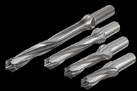
There are a few issues that can serve as possible solutions to these conditions. Let's start with the drill. The most important aspect to consider is the drill point geometry. The smaller the drill size, the more critical it becomes that the drill point geometry is perfectly symmetrical. Bad geometry can cause a drill to "walk" off, giving you a crooked hole, a triangular hole or even a broken drill.
The length of the drill protruding from the collet will greatly affect the drill's ability to track straight. If the drill length is five times the diameter or more, you can expect some problems. But that doesn't mean that lengths less than five times the diameter are immune from problems, either. Always keep all tooling as short as possible for maximum stability. Also watch out for any "stamped" lettering on the shank. This lettering can cause bumps on the shank and can cause the drill to orbit - causing bell mouthing, walking off and other difficulties.
The most obvious error normally encountered is the feeds and speeds used. To avoid this, try using The Machinist Handbook for recommended starting parameters for a given alloy. You can make appropriate adjustments after you get rolling. Most of the above solutions everybody knows about, but sometimes they just don't think about it. When you have problems, always go back to the basics to find the error.
The Big Problem
Now, how often have you heard, "My machine can't hold location. My holes are all over the place!" The most common cause of this situation is not the machine's fault, but the machinist's. To save time, you may sometimes decide that it is not necessary to center drill each location first, because, according to you, "My drill is very short!"
That is mistake number one. The fact that the web of the drill of these small sizes is weak enables the drill to deflect on contact with the workpiece. It needs to be guided into its location. In other words, center drilling is necessary.
Error number two comes into play after you decide that you must center drill before you drill. The error is that you often choose the wrong canned cycle to center drill with. More often than not, machinists will choose the feed in/rapid out cycle (G81). Therein lies the error. The G81 cycle feeds to the given Z depth and then rapids out to the clearance or initial plane. That sounds as though it's doing what it should, right? But stop and think it out for a minute.
What is really going on? The computer is telling the machine to go to a given Z depth. So far, so good. The computer now says that you've completed your move, now rapid out. This is not OK. Because the machine typically lags slightly behind the computer, the machine is still cutting and has not quite reached its destination. Being an obedient piece of equipment, it will do as told and reverse and get out of there. This results in two burr lines in the cone left where the center drill was still cutting when it retreated.
Can you guess what happens when the weak webbed drill comes in and hits the burrs? Right! Crooked holes and holes not on location.
So, how do you solve this dilemma? Use a drill cycle that feeds in, dwells and rapids out (G82). A three-revolution dwell is recommended to insure a clean, burr free cone to start. The magic formula for this dwell calculation is: Dwell = 180,000/rpm. The answer will be the number of milliseconds required to rotate three revolutions at any given spindle speed.
Hopefully, this tip will help you avoid a common problem that bites us all from time to time. Good Luck!
Related Content
3D Printing Enables Better Coolant Delivery in Milling Operations
Just like 3D printing enabled conformal cooling channels in molds, additive manufacturing is now being used to optimize coolant delivery in cutting tools.
Read MoreThe In's and Out's of Ballbar Calibration
This machine tool diagnostic device allows the detection of errors noticeable only while machine tools are in motion.
Read MoreSolving Mold Alignment Problems with the Right Alignment Lock
Correct alignment lock selection can reduce maintenance costs and molding downtime, as well as increase part quality over the mold’s entire life.
Read MoreMoldmakers Deserve a Total Production Solution
Stability, spindle speed and software are essential consideration for your moldmaking machine tool.
Read MoreRead Next
How to Use Strategic Planning Tools, Data to Manage the Human Side of Business
Q&A with Marion Wells, MMT EAB member and founder of Human Asset Management.
Read MoreReasons to Use Fiber Lasers for Mold Cleaning
Fiber lasers offer a simplicity, speed, control and portability, minimizing mold cleaning risks.
Read More




.jpg;maxWidth=300;quality=90)


