
How to Retain Pin Bushings
Simplify pin-bushing retention and reduce machining time by four to one for each bushing hole by implementing a new process.


Switching from cap screws to snap rings for bushing retention saves machining, assembly and repair time while creating a more robust mold.

The old and new design for retaining pin bushings in plastic molds. The old way used a socket screw to pin the bushing in place with one point contact, required three machining operations and changing the setup. The new way uses a snap ring in a groove.
A few moldmakers have adopted a new practice for bushing retention using snap rings, which helps create a more robust, more reliable and more easily serviceable mold. It replaces the conventional retention methods: a small cap screw that overlaps the bushing lip at one point. In the new method, retention forces are distributed uniformly around the ring rather than concentrating on just one point of the bushing lip.
The idea started in the Midwest, where three or four moldmakers have made it standard practice and half a dozen others are in varying stages of converting. Timesavings per mold set average four to five hours for simple molds containing eight to 10 bushings. On bigger, more complex mold sets with 40 to 50 bushings, the timesavings mount up proportionately.


Bushing Retention
Bushing retention locks pin-guide bushings in place in the mold block. The bushings are made of hardened metal, as are guide pins, to resist wear as they rub against each other during mold open/close cycles. If either member did wear, the mating mold halves could get out of alignment and produce bad parts. Likewise, if the bushings shift while the mold is in operation, bad parts could be produced and the molds and machine could be damaged. A safety hazard also could be created by a damaged mold part or machine part breaking loose like a piece of shrapnel.
Snap Ring Process
In the new method, a snap ring holds the bushing in place, and the groove to accommodate that snap ring is machined with the same tool as the bushing hole itself, and on the same centerline. Cutting the groove saves mold machining and assembly time while making the mold stronger (see Bushing Retention: Cap Screw Versus Snap Ring Sidebar). After opening the bushing hole, moldmakers only need to put a different tip—a slotting tool—onto the toolshank already in place, add an orbiting step to the machining program, and they will have the snap ring slot. Total machining time: four to eight minutes, or about one-fourth the time of creating the screw hole. There are no slow machining operations such as drilling and tapping, and design time is not needed to locate the retaining screw.
The new practice hinges on retention by snap rings rather than socket-head screws. The process centers on:
- Machining a snap-ring groove in the counterbore that accommodates the bushing’s lip. Using a tool with interchangeable tips, the grooving step is done on the same centerline as the bushing bore itself, with the toolshank still in place in the spindle.
- Inserting the bushing and snap in the retaining ring.
The snap rings go in and out in seconds following a simple process:
- Compress the snap ring with conventional snap ring pliers.
- Place it in the groove.
- Let go.
One Step Forward
A mold shop using this process originally machined the grooves with a four-flute, high-speed, steel-grooving tool, just after completing the bushing counterbore. Cutting the slot was faster than opening the screw hole, but still left plenty of room for improvement. Although the spindle and mold block remained in position in the X-Y plane for both operations, changing from the boring tool to the groove slotter did take time. Sometimes it also involved raising the spindle or lowering the table to make room for the exchange, which could create an error source. Making the actual cut was slow going to avoid overloading and deflecting the high-speed steel cutter due to lateral forces.
Switching to an interchangeable tungsten carbide cutter on a high-speed steel shank sped up the process considerably. The moldmaker can bore the bushing hole and counterbore with a boring tool, then simply change to a grooving tip for the snap ring groove—all with the spindle, table and toolshank left in position. Then cutting the groove is a matter of making an orbiting cut. Since everything is left in place and the interchangeable tips hold axial and radial positional repeatability to datum within +/- 0.0005 inches, location accuracy of the snap ring groove is ensured.
At one mold shop using the carbide slotter, tool changes averaged 10 to 15 seconds and actual machining of the slot took 12 seconds, half the time as before. They mill the slot with depths-of-cut up to 1/8" in a 1¾" bore.
When the cutters go dull, moldmakers simply replace them rather than regrinding. In the long run it’s cheaper to replace a slot-cutting tip than to get into regrinding. Given the four-week turnaround with regrinders and the shipping times, a mold shop would need to own four cutters to keep just one ready for service at any time.
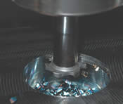
Switching from boring to snap-ring grooving cuts machining and assembly time for bushing retention by four to one in plastic molds. Left: carbide boring tip creates the counterbore to accommodate the bushing’s top lip. Center: switching tips, a 10 to 15 second job with +/-0.0005-inch positional repeatability. Right: slotting tip after completing the snap ring groove.
The old and new design for retaining pin bushings in plastic molds. The old way used a socket screw to pin the bushing in place with one point contact, required three machining operations and changing the setup. The new way uses a snap ring in a groove.


Related Content


Products and Services for Multiple Moldmaking Needs
New year, new technology roundup! Featured here is a collection of product offerings, from profile milling cutters to industry-specific CAD/CAM software to innovative hot work tool steels.
Read More
Three Ways to Accurately Machine Hardened Mold Materials
Three cutting tool design considerations to improve process reliability and cost efficiency when deep-hole drilling molds.
Read More
Tolerancing in Mold Design, Overcoming Cutting Tool Vibration, SPE MTD Updates & More Most-Viewed May Content
Every month, MMT draws inspiration from its diverse readership's wide-ranging interests, from mold design tolerancing to cutting tools and beyond. Here are May’s top 10 most-viewed articles, based on Google Analytics.
Read MoreRead Next

Advanced Toolpaths Improve Cutter Performance in Difficult Materials
Trochoidal toolpaths are available on most CAD/CAM systems, yet are rarely used or even known. By using trochoidal toolpaths and hybrid trochoidal toolpaths you can successfully machine exotic materials.
Read More
Reasons to Use Fiber Lasers for Mold Cleaning
Fiber lasers offer a simplicity, speed, control and portability, minimizing mold cleaning risks.
Read More
Are You a Moldmaker Considering 3D Printing? Consider the 3D Printing Workshop at NPE2024
Presentations will cover 3D printing for mold tooling, material innovation, product development, bridge production and full-scale, high-volume additive manufacturing.
Read More