How Do You Know When It’s Time for New CAM Software?
Mold shops today should not neglect the efficiency that can be gained in the programming department by upgrading their existing software.


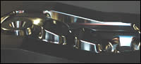
Figure 2: Sample data from a test cut that shows how closely the CAM software license approximated the cut times compared to the actual machining time. For the first rough, less than two minutes were lost over the course of a 38-minute cut. For the last finish operation, which required more than three hours on the machine tool, there was less than 18 minutes of lost time.
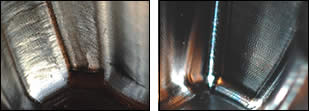
Figures 1a and 1b: The toolpath on the left produces a smeared and dulled finish. The toolpath on the right produced a nice scalloped finish. Figures courtesy of DP Technology.
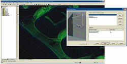
Figure 3: Optimization of bridge movements of the tool for a rest-roughing operation saved approximately 40 minutes of machining time.
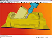
Figure 4: CAM software with the ability to use a 4th or 5th axis to rough the part from multiple approach angles while still automatically optimizing toolpath based on a 3-D stock representation to minimize cutting air.
All 3-D CAM software is the same, right? Unfortunately, this is what many manufacturing managers believe. However, CAM software couldn’t be more different when comparing them face-to-face.
Investing in good moldmaking CAM software is just as important to your business as the quality of the machine and the machine control software, the tools used to cut the mold and toolholders. During machining, if something goes wrong, your result is dependent on the weakest link. There are a lot of factors at work and CAM software is an important component.


So how do you know when you are ready for new CAM software? Following are some factors to consider when determining whether it is time for new CAM software.
Programming Bottleneck
CAM software is usually one of the last things considered, if considered at all, when buying new machines. Many machinists refuse to even discuss how new software will help them. Some common reasons include: the cost of replacing several licenses of software; needing to learn something new; refusing to believe that anything is better than the product they chose years ago; and, not budgeting any time to research CAM.
When a new machine is added to the mix, it is usually faster and will add more capacity to the machine shop. When this happens, all other processes by comparison slow down. Everything that used to have to happen for three machines now has to happen for four of them. Even if one machine is replaced for another, it won’t be a slower machine, so the processes upstream need to be more efficient. Supplying optimized NC programs is crucial to being productive and maximizing the expense of a new machine.
Some companies simply add another license of software and another programmer to keep up. There are times when this is necessary, but this should be considered carefully, as overhead increases. When things get slow again, this company may find itself with a new problem—too much overhead.
If there is 3-D software capable of calculating toolpath more quickly, yet just as efficiently for the machine, this is something that would cost the company once—in addition to training—rather than a yearly recurring fee for additional programmers. Replacing software with more efficient software will add efficiency for all the machines today and tomorrow.
Familiar Ground
When evaluating CAM software, sample parts should be test cut that are familiar to the user. These should include parts that the user has programmed before, knows what needs to be considered, and also is familiar with the finish and the time cycle for machining.
During software demonstrations, the software salesman usually programs sample parts for the user using fairly loose tolerances and stepovers, not showing the true nature of the software in a real-world environment. Some software performance can slow down dramatically when true tolerances are used with proper stepovers. You will want to be familiar with this aspect of the software you evaluate.
Results May Vary
In terms of products, 3-D CAM software is heavily driven by mathematics and the toolpath generated is the determining factor for how fast your machine will cut. In a competitive world moldmaking, faster cycle times, better accuracy and finish is a killer combination. During cutting, the machine’s control will attempt to interpret the points as quickly as possible, but the amount of points and accuracy of the points will determine the resulting feedrate generated on the machine. If these points are not accurate or poorly spaced, the machine will be forced to slow down.
In a test utilizing the same machine tool, same material, same program feedrate, same rpm, same radial depth-of-cut (Rd), same depth-of-cut (Ad), same toolpath type and calculation tolerances, the difference in software can be quite different.
From the photos in Figure 1a, b, the toolpath on the left produces a smeared and dulled finish. The toolpath on the right produced a nice scalloped finish. So why is there such a big difference in the finish of the part when all things are held constant, except for the software that generated the G-code? There are several things happening here that contribute to this result.
Getting in the Fast Lane
Maintaining program feedrates is very important to generating good results on the machine. Many programmers do not even realize that when a program feedrate is entered in the CAM software, the machine may rarely be cutting at that speed. It is true that surface geometry may force the machine to slow down in areas where tool movements are very tight, but overall program feedrates should hold the majority of the time on the machine. Your CAM software may be slowing you down from the get-go with poor mathematical toolpath data.
If the toolpath is not smooth you cannot run fast. Just like driving on a bumpy road, the machine needs a smooth road to drive the tool quickly. Your CAM software is generating this road. If the road is bumpy, the machine runs slower than the program feedrate. If you are not familiar with your CAM software’s performance at the machine, the actual feedrate is displayed on the machine control as it is cutting.
Since programmers usually use the recommended settings from the tool manufacturer for optimal chip cutting, if these values are entered but the machine is rarely cutting at these speeds, the results on the machine will not be optimal. You will not get a nice scalloped finish on the part material. The spindle will be spinning faster than the recommended range for the feedrate and there will be smearing and uneven cutting, which will produce a less desirable finish.
Additionally, if your CAM software is unable to drive the tool at the proper feedrates on the machine, additional machine options such as a high-speed spindle (+20k) may be useless. If you cannot drive the tool to higher feedrates, it makes no sense to have a spindle that allows you to drive the tool more quickly.
Bigger Is Not Always Better
Many programmers and machinists will tell you that the bigger the NC code file, the better the finish will be. This is not true in all cases. It is true that as the calculation tolerance and tool stepover decreases, the amount of toolpath calculated will increase, thereby generating a larger NC file.
However, comparing NC code files of the same tolerance and stepover on the same surfaces from different CAM software will result in NC code files of varying sizes. Typically, a larger file size will result in more unwanted point data that simply confuses the machine and slows down the cutting speed.
Programming Flexibility
CAM software also should help the company accurately quote the machining time for the job. For any given software, the time calculated at the PC and the time it took to run on the machine will always be different.
What you should be looking for is software with consistency. Does the rough cycle cut quickly on one part, but is totally off on another part? Are the finish passes always quite slow compared to the calculated time cycle from the software? If so, this makes it hard to accurately quote the job.
There is a fine line between quoting too high and not getting the work, and quoting too low and not making any money. You don’t want the machine to take much longer to actually cut when compared to the estimated cycle time from the CAM software license.
This sample data from the test cut in Figure 2 shows how closely the CAM software license approximated the cut times compared to the actual machining time. For the first rough, less than two minutes were lost over the course of a 38-minute cut. For the last finish operation, which required more than three hours on the machine tool, there was less than 18 minutes of lost time. This means the tool was running at the program federate—or close to it—nearly the entire time, generating optimized chip removal and preserving machine costs.
For this part, contributing factors include mathematics, intelligent roughing and automated optimization of toolpath. CAM software with intelligence to utilize the best approach method for entering and exiting the cut is essential to programming efficient toolpath. Not having options limits the user to the capabilities of their existing software out-of-the-box. In Figure 3, optimization of bridge movements of the tool for a rest-roughing operation saved approximately 40 minutes of machining time.
Even though rapid movements seem like they would be faster, the machine never gets to the full rapid rate and must retract in and out of the part, which results in a slower toolpath on the machine.
Another new feature that would interest moldmakers today is CAM software with the ability to not only rough from predetermined stock, but to be able to utilize a 4th or 5th axis to rough the part from multiple approach angles. This significantly reduces air cutting and helps generate programs more quickly for moldmakers that deal with undercut areas (see Figure 4). Any companies looking to make rubber molds, molds with undercuts, or any type of artistic piece like statues, etc., would gain great efficiency from this capability.
Summary
Overall, shops today should not neglect the efficiency that can be gained in the programming department. Different approaches to software will yield different results, helping grow the company rather than handcuffing it. Learning new software requires some time and cost, but will make your programmers better in the long run by exposing them to different products and new capabilities that they may not have realized existed. This makes them more prepared when programming new jobs or reprogramming jobs that were cut in the past without optimal results.
CAM software also should be considered any time a new machine is purchased. The developments in CAM capabilities every year are quite drastic, so several years out of the marketplace will likely yield many results that can have practical use in your shop to lower costs and increase efficiency.


Related Content

How to Select a Mold Temperature Controller
White paper shares how cooling channel analysis, which collects maximum pressure drop, total flow rate and heat dissipation, eases the performance evaluation of mold temperature controllers.
Read More
Mold Innovations Power Unique Auto Lighting Elements on Hummer EVs
Diamond machining, electroforming of micro-optical inserts and modified latch-lock system help injection molds produce unique forward lighting elements.
Read More
New Innovations in Mold Design, Milling Cutters, 3D Scanning
MoldMaking Technology compiles a number of digital-only products from the past month, including mold design software, laser metrology 3D scanners, milling cutters and more.
Read More
Products and Services for Multiple Moldmaking Needs
New year, new technology roundup! Featured here is a collection of product offerings, from profile milling cutters to industry-specific CAD/CAM software to innovative hot work tool steels.
Read MoreRead Next

Software Packages Streamline Design Seamlessly
New software seats provide quicker design and toolpath generation—resulting in increased throughput without spending a lot of money.
Read More
CAM Technology Trends
More than the products themselves, the CAM industry is changing the way it does business and moldmakers should take note.
Read More
Challenges to Five-Axis Machining for Moldmaking
When considering five-axis machining you must consider your goal for using five-axis machining on molds: to machine the complete part with the shortest cutters possible.
Read More