
From the Field: The Right CAD/CAM Makes New Mold Manufacture Easier and the Entire Process More Efficient
Fine, tiny detailing demanded by model railway enthusiasts requires moldmaking tolerances in manufacturing scale models that are often tighter than those in the automotive industry. With the right CAD/CAM system creating the mold around the designed product takes approximately 30% less time than it did with the CAD/CAM system PECO used before switching to VISI.


PECO manufacturers the largest range of model railway track in the world, distributing to around 450 model shops across the UK and exporting to over 30 countries worldwide. New Products Development Manager Paul Hitchcock says PECO is renowned for quality and detail on its plastic injection molded track and accessories.
When a model is scaled down it becomes miniscule and can be extremely difficult to produce, but he says using Vero Software makes it easier to achieve. Working with a range of VISI modules not only provides greater accuracy, but also saves 30% of design time, while saving the toolroom CNC Programmer even more time during the manufacturing process.


The materials used depends on what is being asked of the finished mold, and includes Uddeholm ‘Orvar Supreme’ steel for the insert molded track tools, aluminium, HASCO 2311- 2312, and brass for interchangeable cavity inserts. The products are made from a range of polymers including polythene for the track, ASA, acetal, nylon and HIPS.
Tolerances for the track are extremely important, according to Engineering and Development Director Ben Arnold. “We produce a lot of insert molded products with metal components that have their own tolerances. The tool has to sit very neatly and snugly around them to ensure there is no flash along the sides of the rails on the finished molded track product. In that respect, some of the tolerances for our tools are tighter than those I worked with in the automotive industry.”
Paul Hitchcock says the rail parts have to touch the tools precisely in the correct place to be right. “If they don’t touch we’d get flash and that isn’t acceptable, so in reality we’re working to the nth degree” of precision. While mold tools for most ‘Lineside’ products such as station buildings and signals are accurate to 10 to 20 microns, they generally use around 5 microns as a standard.
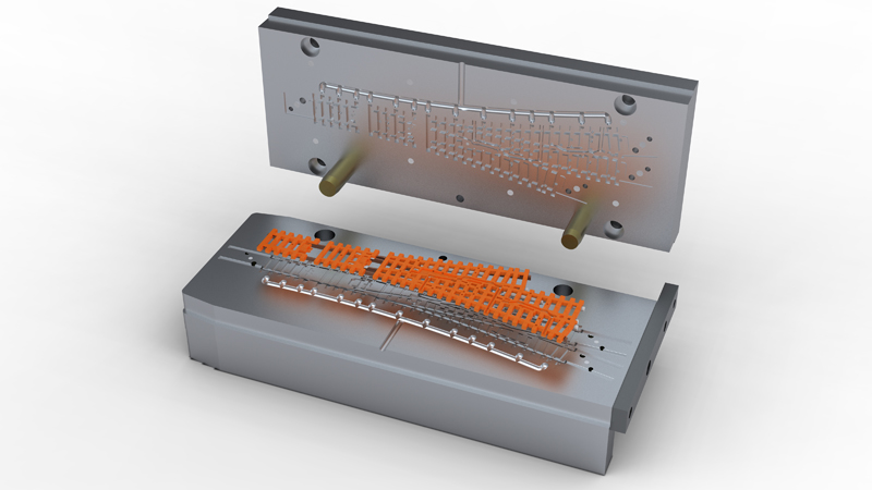
Paul Hitchcock uses VISI Modelling, VISI Mold incorporating VISI Catalogues, and VISI Electrode, to design the mold tools, having originally imported the product as Solidworks data. The track needs a bespoke tool design, so he merges it with a blank tool template, creates the cavities and adds ejector pins, guides and other standard components. For many other products he utilises VISI to design tools based on Hasco or Meusburger mold stacks.
He says creating the mold around the designed product takes approximately 30% less time than it did with the CAD/CAM system they used before switching to VISI in 2010. “With the number of modifications and changes we go through during manufacture the history tree of our previous system caused frequent problems, But VISI provides concurrent design and manufacturing, meaning the design and toolpaths are easily modified.”
Features of VISI Modelling that stand out for him include being able to import a model without affecting previous versions. “Also, it’s so simple to move a face, cut the body and create cavities.” He finds the layer structure to be particularly useful in migrating files to Autosketch in DXF format.
VISI Mold’s ease of creating cavities and placing standard components, even into difficult shapes, gives him confidence that the information he passes on to the Toolroom is correct. Prior to using VISI he would sometimes feel that certain aspects of a mold design were not complete and may not work, “But now I know that if the mold is made to my design it will work.”
And he says VISI provides another valuable facility. “If a cavity has been cut away without us noticing a face needed drafting, we can simply go back to the model of the mold tool and add draft to the appropriate face, knowing nothing else will be affected.”
When the mold design is complete, the process passes to the CNC programmer who manufactures the electrodes using VISI Machining 2D and 3D. “Some of our copper electrodes are so small with such fine detail that we have to separate sections out. That used to cause a lot of trouble with our previous system, as we’d lose the detail by suppressing something that a number of other aspects are dependent on. But now we just extract what we want, without having to worry about everything else that’s generated the part,” says Paul Hitchcock. “VISI has totally changed the way he works, in that he simply extracts the detail or faces using VISI Electrode. Previously he would frequently have to make a 2D sketch from my 3D model, and use that to produce the electrodes.”
The machining part of the operation is made faster by the ability to have a number of instances open at any one time. “We can set a calculation running and then move on to another and another with each toolpath calculating independently. With our previous software we could only set one and have to wait – sometimes half an hour – for it to finish before we could move on. So we save a considerable amount of time on this part of the operation, too.”
Investment in machinery includes a Mikron high speed machining centre for making the electrodes, a Sodick CNC 4-axis spark eroder with linear motors, and 11 injection molding machines, mainly Engel and Arburg. They also have a laser ablation machine which has been instrumental in producing molds for tiny ‘N’ Gauge ‘Lineside’ bikes. The mold was created in VISI, saved as an STL file and imported directly into the laser machine for machining.
“VISI has made the manufacture of new mold tools much easier and the whole process more efficient.”


Related Content

The In's and Out's of Ballbar Calibration
This machine tool diagnostic device allows the detection of errors noticeable only while machine tools are in motion.
Read More
The Trifecta of Competitive Toolmaking
Process, technology and people form the foundations of the business philosophy in place at Eifel Mold & Engineering.
Read More
Hybrid Milling/Drilling Machine Reduces Total Mold Machining Time
MSI Mold Builders now squares, plus drills and taps eye-bolt holes on 50% of its tools in a single setup using a five-axis milling/drilling center with a universal spindle.
Read More
Women Impacting Moldmaking
Honoring female makers, innovators and leaders who are influencing our industry's future.
Read MoreRead Next

Are You a Moldmaker Considering 3D Printing? Consider the 3D Printing Workshop at NPE2024
Presentations will cover 3D printing for mold tooling, material innovation, product development, bridge production and full-scale, high-volume additive manufacturing.
Read More
Reasons to Use Fiber Lasers for Mold Cleaning
Fiber lasers offer a simplicity, speed, control and portability, minimizing mold cleaning risks.
Read More
How to Use Continuing Education to Remain Competitive in Moldmaking
Continued training helps moldmakers make tooling decisions and properly use the latest cutting tool to efficiently machine high-quality molds.
Read More