
Four Key 5-Axis Programming Developments for Moldmakers
Recent advancements in CAM software offer new benefits while maintaining ease of use.
Figure 3 Tire mold.
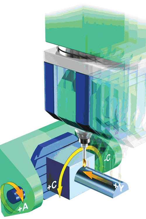
Figure1b Movements of machine axes with different kinematics.
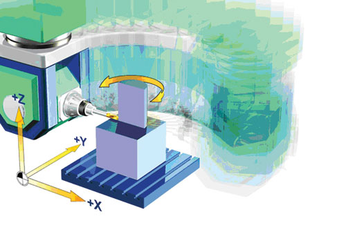
Figure 1a Movements of machine axes with different kinematics.
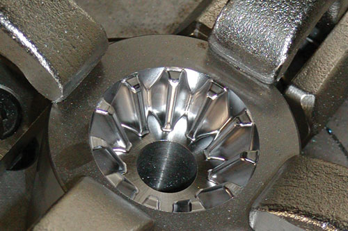
Figure 2 Forging die of a bevel gear.
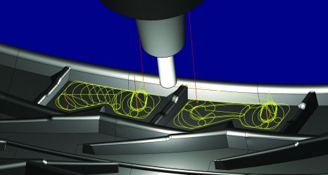
Figure 4 Material removal and shape offset roughing and finishing.


Five-axis machining strategies for mold and die manufacturing enable the continuous machining of significantly larger areas with shorter tool lengths on vertical walls or steep walls, thereby improving process parameters and surface quality. Normal-to-surface milling using bull-nose tools and swarf cutting allow higher stock removal rates due to the greater step-over distances between paths as compared to machining with ball mills. Chamfers, shaped grooves and engravings can also be manufactured much more efficiently. These and other benefits—such as reduced setups and shorter tool lengths—have been the traditional justifications for the use of 5-axis technology.
Now further developments in CAM software provide even more benefits while maintaining the ease of use of 3-axis programming software. Four of these developments are: (1) automatic tool axis adjustments to avoid collisions, (2) automated rest machining, (3) automatic indexing and (4) shape offset roughing and finishing.
CAM and 5-Axis Machining
In order to make generating an NC program as easy as possible, you need a CAM system that fully exploits the performance range of each machine tool and takes the machine kinematics into account (see Figures 1a,b). Compared to 3-axis milling, the movements of the tool reference point and the movements of the machine’s linear axes (pivot point path) are different during 5-axis simultaneous machining, as movements of the rotary and tilting axes result in compensation movements in the linear axes. These compensation movements depend on different factors—such as the geometry to be machined, the setup position and the machine’s kinematics.
During 5-axis machining, the focus is on cost-effective milling, not on the execution of spectacular machine motion. The best possible results are achieved when a machining job requires as little movement as possible. For example, one test shows that a changed setup position reduced machining time by one-third. Reducing movements of the machine axes to the minimum also reduces machine loads and thereby compensatory shifting due to heat generation and wear. This prolongs machine life and increases machining precision. The key to successful milling projects is striking the proper balance between programming effort, cutting time, machine movement, surface finish and tool usage. These factors may play different significance depending upon the shop in question.
1. Automatic Collision Avoidance
Today there is a method for the easy and reliable programming of 5-axis simultaneous machining for mold and die manufacturing. In addition to real-world strategies for tool orientation, fully automated collision avoidance is at the core of this 5-axis technology.
For complex milling areas, it is typically difficult, and sometimes even impossible, to find a constant definition for tool orientation. 5-axis simultaneous movement with fully automated calculation of tool angles solves this problem. Traditional programming solutions require that a programmer create sketch geometry to define rotary axis movement. The resulting milling operation must be simulated to check collision. This process must be repeated until the proper tool inclination is correctly guessed by the programmer. Modern CAM software should calculate a collision-free toolpath from the beginning, taking into account the tool, tool holder, spindle geometry and machine kinematics. The rotary axis of the machine tool should be automatically adjusted to minimize machine movement while completing the necessary toolpath.
2. Rest Machining
Traditional rest machining is a labor intensive process that has typically involved mentally dividing a job into many separate areas and defining machining orientations for each one. Today, rest machining strategies are available that mathematically define the minimum required 3+2 machining orientations and the resulting toolpath for all of the separate areas of a project in a single operation.
This significantly reduces programming time for complex geometries. If a collision is detected in one of the rest machining areas during toolpath calculation, minimal simultaneous 5-axis motion can be activated and the tool axis adjusted to avoid the collision—all without user intervention. This optimizes the machining time by maximizing the use of 3+2 and minimizes the 5-axis simultaneous motion.
3. Automatic Indexing
It is now possible to automatically control both rotation axes independently, so only one of the two rotation axes is used to achieve continuous, collision-free machining. This 4+1 machining style is particularly advantageous because the rotation axes are typically different in terms of technical capabilities and precision. This may be because of different masses to be moved or different drive power. Limiting the movement of the less dynamic axis improves machining times and surface finish.
Some of today’s CAM solutions go one step further and provide automatically indexed axes. The tool angle is calculated in such a way that the tool orientation within a milling area on the surface is not changed. If necessary, the milling area can be automatically subdivided further, or local simultaneous movements can be generated.


In one example, a metal injection mold with more than 350 flat and more than 370 steep rest material areas with different angles was machined in a single operation. All the user had to do was define the preferred lateral tilt. This significantly cut the required programming time.
The forging die for a bevel gear (see Figure 2) was machined on a 3-axis machine tool using a spiral cutting motion that circled the part 273 times. By tilting the milling tool to the center of the cavity, it was possible with comparable 5-axis (actually 4+1) machining strategy to halve the length of the tool tip, thereby increasing the rigidity by a factor of 8. This allows significantly higher process parameters with less risk of tool breakage and chatter. However, when using 4+1-axis machining, the C axis required 273 revolutions with 22 braking and acceleration processes, which represents a major strain and results in the danger of erroneous synchronization of the axes on less dynamic machines.
Automatic indexing enables another machining strategy that moves only once around the C axis in imperceptibly small steps in a single 360° rotation—a machining strategy that, compared to conventional 5-axis machining, can always maintain the programmed feedrate even when using a slow worm drive. And because unnecessary movements are avoided, this process is also easy on the machine, which results in significant cost savings.
4. Material Removal and Shape Offset Roughing and Finishing
Modern high-performance roughing algorithms have proven ideal for hard milling applications. These volumetric roughing processes prevent the cutter from cutting deeply in corner areas of having a sudden change in direction. These new technologies also provide ideally distributed milling paths, climb only milling strategies and dynamically adjusted feedrates. They have been proven to allow for the most efficient removal of large volumes of material and the constant cutter load extends both tool and machine life. Today, this approach is available for 5-axis applications for geometries with concave or convex floor conditions using shape offset strategies.
Z-level roughing and Z-level finishing are the traditional programming approaches that have been used successfully for years. In some applications, such as tire mold programming (see Figure 3), the toolpath projected on the geometry by Z-level have proven to be inefficient due to a non-constant floor condition resulting in multiple retracts. Shape offset roughing and finishing, named due to the toolpaths offset from a shaped surface rather than projected at Z-level, overcome this issue and allow for the inclusion of bull-nose tools and end mills. A programmer need only select the floor of the surface, and from this input, they may choose to rough, floor finish, or both wall and floor finish. Since the toolpath accounts for the shape of the surface bull-nose and end mills may be employed and the tool is constantly engaged in material thereby improving cutting conditions and minimizing retracts (see Figure 4).
Summary
Clearly, there is no “one size fits all” approach that can be used to achieve ideal milling projects. Successful projects require that a skilled programmer properly balance a large number of factors to achieve the desired result. Due to this strange calculus, experienced programmers will always be the driving force at the most commercially successful shops.
Modern CAM software can do much to shorten the learning curve for programmers with less experience while providing a competitive edge for the veterans. This is accomplished by minimizing the number of factors that must be considered. By providing mathematically calculated tool orientations, a high level of process assurance prior to simulation, forward-thinking toolpath algorithms that reduce the strains on a machine tool’s rotary axis and the best results for large volumes of material removal, successful 5-axis milling projects are more easily be achieved


Related Content

Leading Mold Manufacturers Share Best Practices for Improving Efficiency
Precise Tooling Solutions, X-Cell Tool and Mold, M&M Tool and Mold, Ameritech Die & Mold, and Cavalier Tool & Manufacturing, sit down for a fast-paced Q&A focused on strategies for improving efficiencies across their operations.
Read More
CAM Automation Increases Mold Production, Quality
Mold builder switches CAM software package after 20 years to take advantage of innovative programming strategies that reduce mold machining programming and processing times.
Read More
Tolerancing in Mold Design, Part 2: Using GD&T to Address Conventional Tolerancing Issues
Mold designers can achieve a single interpretation of workpiece functionality when following the American Society of Mechanical Engineers Geometric Dimensioning and Tolerancing standard.
Read More
Products and Services for Multiple Moldmaking Needs
New year, new technology roundup! Featured here is a collection of product offerings, from profile milling cutters to industry-specific CAD/CAM software to innovative hot work tool steels.
Read MoreRead Next

How to Achieve Economical Five-Axis Milling
Although moldmaking has not had great incentives to invest in five-axis technology like the aerospace industry, there are still many reasons for moldmakers to adopt five-axis machining, and there are a few interesting software functions that help to make five-axis programming economical.
Read More
How to Use Strategic Planning Tools, Data to Manage the Human Side of Business
Q&A with Marion Wells, MMT EAB member and founder of Human Asset Management.
Read More
Reasons to Use Fiber Lasers for Mold Cleaning
Fiber lasers offer a simplicity, speed, control and portability, minimizing mold cleaning risks.
Read More