Five-Axis Machining Software Offers Speed and Flexibility
Improvements in five-axis machining software are lowering the barrier for adoption by moldmakers.


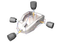
Five-axis drilling.
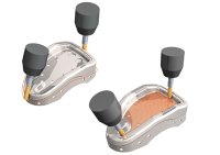
Five-axis profiling and rastering.
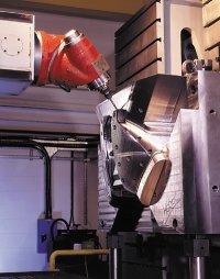
Five-axis capabilities that were once only available on large-scale machines are now becoming available on the smaller machining centers used for moldmaking.
Five-axis machining has been used in aerospace applications for many years, but until recently, the technology has made little impact on toolmakers. However, new developments in machining software have made programming for five-axis operations much easier, with the result that the moldmaking industry is showing an increasing interest.
A number of other reasons also have contributed to this change in attitude. First, the price of five-axis machines has been falling steadily and this trend is expected to continue. In addition, five-axis capabilities that were once only available on large-scale machines for the aerospace industry are now becoming available on the smaller machining centers used for moldmaking.


Two distinct types of machines are now being offered: those that are, effectively, smaller versions of the machines used in the aerospace industry, with all five axes of movement being generated through changing the orientation of the head, and those that have a fixed orientation for the head, with the extra two axes being produced by tilting and/or rotating the workpiece.
Five-Axis Positional Machining
In the aerospace industry, there has been considerable use of continuous five-axis machining, in which the relationship between the cutting tool and the surface being cut is constantly changing in all five axes. In contrast, the most commonly used type of five-axis machining in the moldmaking industry is positional five-axis machining. With this technique, which is also known as 3-plus-2 machining, the head is oriented into a series of positions and machining carried out as a set of discreet operations. As with continuous five-axis machining, positional five-axis machining enables shorter cutters to be used since the head can be lowered toward the job and the cutter oriented toward the surface. As a result, higher cutting speeds can be achieved with no loss in accuracy.
A second major benefit is the ability to machine complex shapes in a single setup. This obviously saves time compared to performing the job in a series of setups. Furthermore, with multiple setups, there is always a possibility of incorrect alignment each time the part is moved.
Both of these benefits have been experienced at Buckinghamshire, UK-based moldmaker and precision engineer, A.F. Gaskin Ltd. Ray Gibbs, production manager at Gaskin, explains, "Since there are no time or quality penalties in repositioning the work, we are able to exploit the advantages of machining using multiple work planes. Using our five-axis software, we can look at a job and work out how it can be positioned in such a way that we can maximize tool access.
"The result has been that we can machine the surface in areas that would previously have been impossible to access economically," he continues. "In addition, difficult surfaces that would have needed long series cutters are now simple. Easier access is allowing us to use shorter tools, resulting in improved surface finish and a reduction in the number of post machining operations, including EDM."
Gibbs also highlighted another real benefit of five-axis machining that was not part of the original purchasing decision, but has become apparent with use. Even though the machine was operating at a higher work rate - using faster speeds and feeds - the increase in productivity was accompanied by improved tool life. Gibbs' explanation is that they could avoid using only the bottom of the cutter and so give more efficient machining and more even wear over the cutting surface.
Another area where five-axis machining can give huge timesavings is the drilling of holes. While this may seem trivial in comparison to the complexity of machining a complex core or cavity, drilling a series of holes with different compound angles is extremely time consuming. If a three-axis machine is used, a different setup must be used for each hole. In addition to the extra time required, it is very easy to make a mistake when changing between a long series of complicated setups. With a five-axis machine, the head simply has to be oriented along the correct axis and the drilling can be completed much more quickly.
To simplify things still further, modern CAD systems allow manufacturing information to be stored along with the geometry as the hole is created in the design. Details can be included, such as whether a tapped or drilled hole is required, whether the hole has a set depth or whether it passes completely through the component. This information can be interpreted by the machining software and default strategies and values (speeds and feeds) applied automatically.
One company that has made use of this functionality is Beaubury Precision Moulds Ltd. of Aylesbury, UK - a specialist in the manufacture of blow molds for the cosmetics, household products and auto-motive industries. Blow molds require extensive water cooling to allow maximum heat removal and so reduce cycle times. As a result, a lot of drilling is required to produce the coolant channels. Using a five-axis machine for this work has helped the company reduce the time to manufacture a mold from 12 weeks to typically between four and six weeks.
There are several factors that have made positional rather than continuous five-axis machining the preferred approach for most moldmakers. A study undertaken last year by U.S. analysts CIMdata (Ann Arbor, MI) - a consulting and research firm - found that around three quarters of moldmakers with five-axis capabilities used this technique. One of the main reasons is that machining can usually be undertaken more quickly. Once the correct orientation has been achieved, the fact that the head is then fixed means that it is possible to operate at high spindle speeds. With continuous movement of the head, it is difficult to operate at higher speeds because of the inertia that has to be overcome. In addition, once the new workplane has been set, it is easy to check for possible collisions or gouging. These calculations are much more difficult with continuous five-axis machining.
CAD for Five-Axis Machining
The CAD requirements for five-axis machining are fundamentally the same as for three-axis machining. However, these good practice procedures should be applied even more rigorously, as there is more likelihood that problems with the CAD model will cause machining difficulties. Furthermore, the potential cost of repairing any damage to the machine will almost certainly be higher with a five-axis machine.
The most critical aspect is the tolerance used within the model. The modeling tolerance must be set at a finer level than the planned machining tolerance. Adjusting the machining tolerance when manufacturing a poor-quality model will only mean that the defects will be machined more accurately.
Another key issue is the trimming of the various surfaces that go together to make up the model. Overlaps or gaps between surfaces can cause a problem for three-axis machining, but will be even more serious with five-axis machining since the cutter can be oriented to move between any gaps. Again, this can be a common problem if data is translated between systems with different tolerances set in the sending and receiving systems.
A final recommendation, which should again really be followed for all machining operations, is to ensure that the CAD model contains all of the features that need to be machined. In the past, it was common for fillets to be left out of the CAD model and to be formed implicitly by the cutter during machining. With modern CAD systems, filleting is both much easier and quicker. Forming these features by machining inevitably involves the risk that the result will not be that which is required. Also, this approach puts excessive load on the cutter and on the machine tool, which will result in excessive wear or even breakages.
Continuous Five-Axis Machining
Continuous five-axis machining is currently less popular in the moldmaking industry, although there are now signs of increased use in some areas. With this technique, there can be simultaneous movement in all five axes. The main challenge for the moldmaker using this approach is to ensure that the head does not collide with the job as the orientation is changing. This is less difficult when machining a core, but can provide a major challenge when machining inside a small but complex cavity.
One of the most common techniques promoted for continuous five-axis machining is based on keeping the cutter approximately normal to the surface being machined. While this approach has benefits in the aerospace industry, it is less appropriate for moldmaking, since the parts being machined, and the individual details within them, are typically much smaller.
Firstly, machining normal to the surface will require the machine head to travel a greater distance than necessary when machining a convex surface and so will increase machining times. It may be found that the normal position is inaccessible by the machine head, while, in other cases, it will be impossible to maintain the 90' angle without a collision with another section of the model.
Secondly, maintaining the cutter at a 90' angle to the surface of the part means that only a small part of the cutting surface of the tool is ever used. As a result, tool life is much shorter. Also, the tool tip travels a shorter distance at a given rotational speed than the full width of the cutter, so the material removal rate will be lower when using ballnose cutters.
In contrast, some software can generate five-axis toolpaths based on machining through a point or to a point, or to or from a line. The software incorporates automatic adjustment of tilt angles for both lead and lag. Lead is measured in the cutting direction; lean at right angles to the cutting direction.
Control of both lead and lag can give better cutting conditions, while the lean angle is used to avoid collisions. In addition, some software features routines for the calculation of gouge-free leads and links as the machine tool moves between the various surfaces within a part. These ensure that gouges are prevented and that collisions do not occur between the cutter and the part being machined.
Another important advantage of this five-axis machining software is that it works with the full range of different cutting tools, including endmills; tapered cutters; and ballnose, tipped-radius and off-center, tipped-radius cutters. Some of the systems currently available are limited to using only ballnose and endmill cutters, which are not always the most efficient, especially when roughing.
As stated above, most moldmakers will use 3-plus-2 machining for the majority of their work. However, there are a number of instances where continuous five-axis operation will be required.
One example is when trying to machine a sharp corner along a complex profile. With three-axis machining, a ballnose cutter will have to be used. This will leave a small fillet in the corner - rather than a sharp corner - that will need to be removed by hand. In contrast, by using an endmill and five-axis machining, it is possible to machine the sharp corner directly. The amount of hand finishing required will be minimal, giving considerable timesavings and helping to ensure accurate components.
Trimming is another area where continuous five-axis operation can be required. This is of particular importance in the finishing of composites. The key benefit is again the ability to undertake the complete operation in a single setup rather than having to use multiple setups. Five-axis trimming also gives the ability to cut at a fixed angle to the surface and so produce a better appearance on the product without as much hand finishing.
The Future
The continued development of reliable, easy-to-use software for five-axis machining will remove another barrier to the adoption of this technology by the moldmaking industry.


Related Content

Leading Mold Manufacturers Share Best Practices for Improving Efficiency
Precise Tooling Solutions, X-Cell Tool and Mold, M&M Tool and Mold, Ameritech Die & Mold, and Cavalier Tool & Manufacturing, sit down for a fast-paced Q&A focused on strategies for improving efficiencies across their operations.
Read More
How to Produce More Accurate Molds and Reduce Rework
Patented micro-milling process for manufacturing steel plate flat and parallel helps mold builders shorten mold build times and increase accuracy.
Read More
Control Helps Push the Limits of Five-Axis Micro Mold Machining Accuracy
Toolmaker quickly meets the demands of critical medical device manufacturers with a new five-axis machine tool equipped with the right control technology.
Read More
OEE Monitoring System Addresses Root Cause of Machine Downtime
Unique sensor and patent-pending algorithm of the Amper machine analytics system measures current draw to quickly and inexpensively inform manufacturers which machines are down and why.
Read MoreRead Next

Simplified Approach to Complex Five-Axis Machining
As multi-axis machine tools become more complex, CAM software systems must provide a more elegant way to program them.
Read More
How to Use Continuing Education to Remain Competitive in Moldmaking
Continued training helps moldmakers make tooling decisions and properly use the latest cutting tool to efficiently machine high-quality molds.
Read More
How to Use Strategic Planning Tools, Data to Manage the Human Side of Business
Q&A with Marion Wells, MMT EAB member and founder of Human Asset Management.
Read More