
Examining Mold Surface Quality
High-quality rotary encoders can help improve the quality of milled surfaces.

Complex workpieces like this one require all possible combinations of axis motion during milling.Images courtesy of Heidenhain Corp.
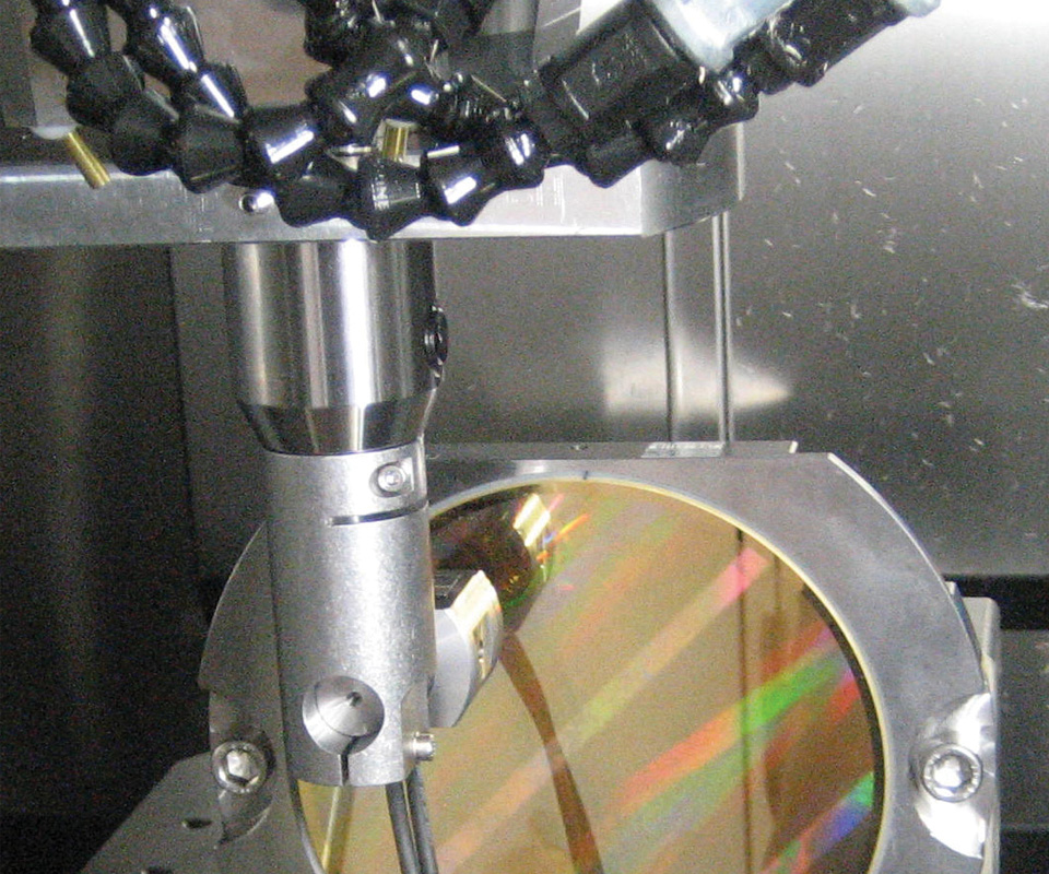
A grid encoder permits non-contacting determination of the contouring deviations between the tool center point and machine table in the plane of the two moved feed axes.
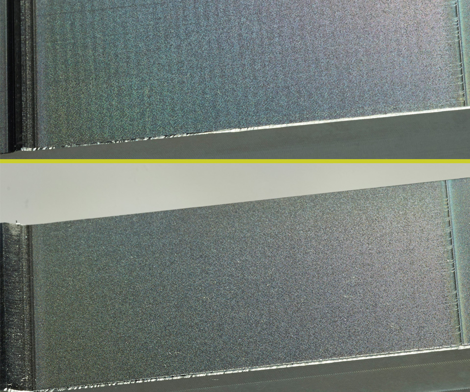
On the top milled aluminum workpiece, the greater interpolation error of rotary encoder 1 caused waves of about 1.5 mm, which are visible as undesirable shadows. Rotary encoder 2’s three-times-lower interpolation error produced a near-perfect surface in the workpiece on the bottom.
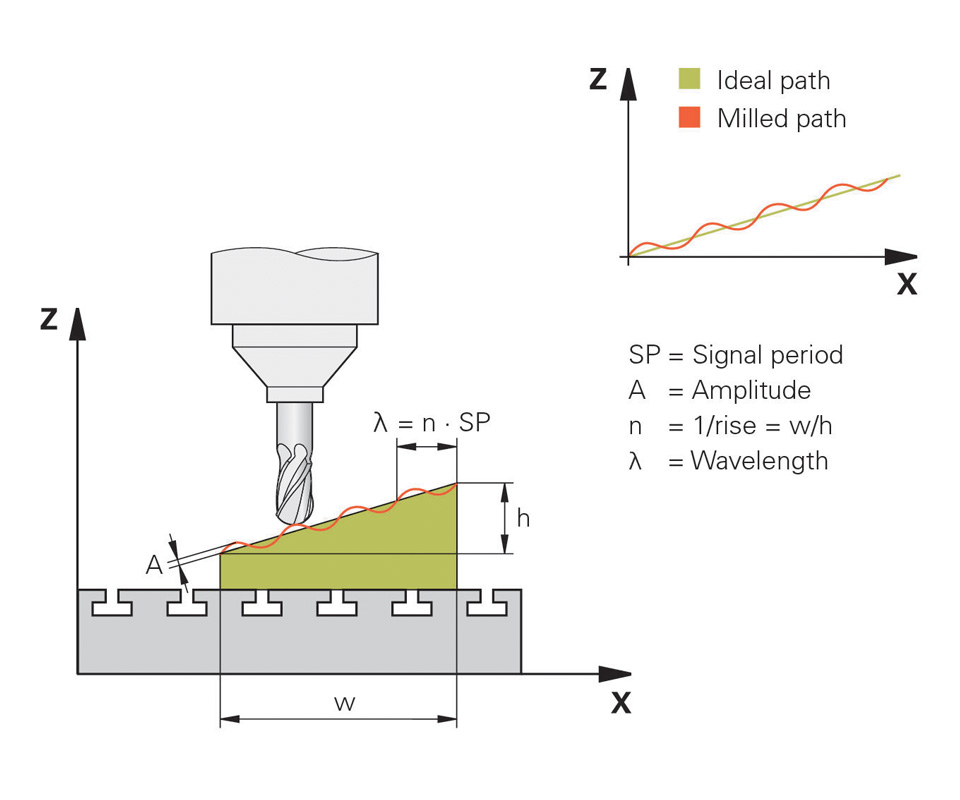
Fig. 1 - The inclination in this milled workpiece can cause an n-fold stretching of the signal period in the encoder’s feedback to the control to appear in the tool path, which is similar to a ripple. While the axis in the Z direction (h) moves by only one signal period, the X axis moves n times more (w). A wave appears on the inclined workpiece surface with a wavelength that corresponds to the n-fold signal period of the Z-axis encoder.
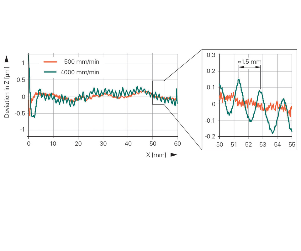
Fig. 2 - This graphic shows measuring results for rotary encoder 1 with a three-times higher interpolation error at two different contour speeds. At a feed rate of 4,000 mm/min., wave-shaped contouring deviations occurred in the Z direction. The wavelength is about 1.5 mm.
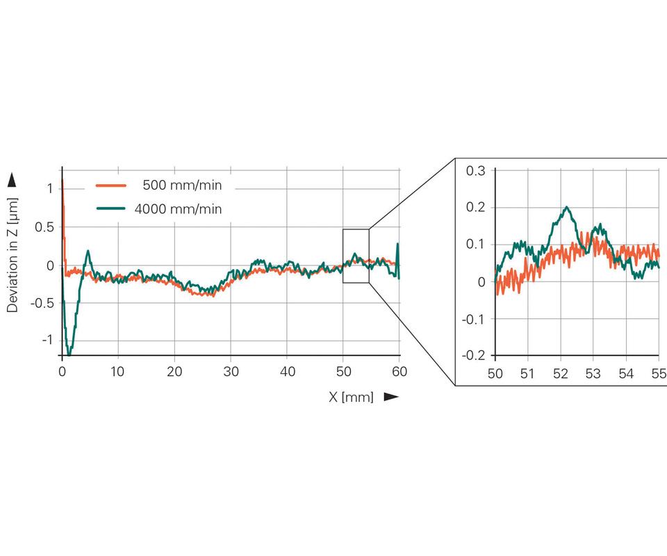
Fig. 3 - This graphic shows measuring results for rotary encoder 2 with a lower interpolation error. Because the interpolation error is less by a factor of three, no superimposed waves occurred.


Flawless surfaces are a frequent goal in metalcutting, particularly in mold manufacturing. Manual polishing costs can be avoided when milling alone delivers high surface definition. An important factor for achieving such good milling results is the type of measuring technology used with the milling machine, which can impact that surface quality.
Such measuring technologies include linear and angle encoders within the machine tool that define cutter position, as well as rotary encoders in the servomotors that contribute to control of the cutting speed. Together, these encoders act as a check and balance in the machine’s control, helping it to maintain the proper speed and position of the cutting tool, and therefore enabling that cutting tool to achieve good surface finishes. Oftentimes, if the machine’s control is also equipped with dynamic control options like adaptive feed control, cross-talk compensation or kinematic compensation, little or no rework is required.


Encoders are composed of a sensor and a scale that provide position and speed feedback to a machine’s controller. The more precise the scale’s graduations, the better the encoder. The heart of an encoder is its measuring standard, usually in the form of a grating with typical line widths of 0.25 to 10 microns. These precision graduations are a decisive factor in the function and accuracy of all encoders. They consist of lines and gaps at defined intervals with very little deviation, forming structures with very high edge definition. One line and gap combination equals one signal period.
Measurement errors can limit an encoder’s performance and result in poor machining quality. It should be noted that the lower the signal period (the finer the graduations of the encoder), the less interpolation error can be expected. Interpolation error (a digitizing error of the electronic signals) by the encoders can sometimes lead to undesirable, recurring irregularities on the machined surface. The human eye can clearly detect deviations within a wavelength of 0.5 to 5 mm. These deviations are visible as shadows or contrast fluctuations, and in mold manufacturing they are the cause of time-consuming and costly refinishing work.
Deviation Effects
Workpieces with complex geometries, like the one shown in the image on the facing page, require five-axis machining, and all possible combinations of axis motion. If an inclined or curved machining surface is manufactured through the interpolation (precise, synchronized movement) of multiple NC axes and the interpolation error is not properly compensated for, the result of that error will be seen directly on the workpiece.
This is particularly apparent when an inclined surface with a shallow angle is machined. The interpolation error in one signal period of the encoder in the Z direction can become visible by projection on the inclined workpiece surface (see Figure 1).
Contouring Accuracy Test
A controlled linear-feed axis setup is usually comprised of a servomotor, a precision-ground ballscrew, the axis structure and the axis measuring technology. This measuring technology is in the form of an encoder that determines the position of the axis structure. The servomotor’s rotary encoder relays the actual speed of the axis to the control in addition to a position measurement (turns of the ballscrew) that some controls then compare with data from the other encoder as a safety feedback. This combination is usually referred to as a closed-loop feedback system and often eliminates the need to “warm-up” a machine before quality parts can be produced. Since all machine structures have some error (because of fit between mating parts and, eventually, wear), a compensation factor can be entered into the control as an error map for each axis independently.
In a test conducted with a high-performance, five-axis machine tool, it was possible to isolate the cause of the potential surface irregularities. This test evaluated rotary encoders in the servomotor of the Z axis where each rotary encoder reported different interpolation errors. All of the machine’s linear axes were equipped with linear encoders in order to continuously achieve high-positioning accuracy and minimize the effects of thermally-induced length changes of the recirculating ballscrew. Because these linear encoders have such a small grating pitch, they produce interpolation error of significantly less than ±100 nanometers, and this would not cause any visible surface waves. Therefore, any form error (that is, errors in surface metrology features such as straightness, flatness, circularity, sphericity and cylindricity) identified in this test would be from the influence of the interpolation errors from the two rotary encoders.
In order to be able to separate the effects of the machining process and the movement of the tool center point, a grid encoder, which dynamically tests the contouring accuracy of CNC machine tools, was used to determine the contouring deviations prior to machining (an error map). The grid encoder (see image) permits non-contacting determination of the contouring deviations between the tool center point and machine table in the plane of the two moved feed axes. The Z axis of the machine is relevant in this test because the rotary encoder on the servomotor is varied on the Z axis. Here, two mounting-compatible rotary encoders were used, each with 2,048 graduations on the circular scale. Rotary encoder 1 has an interpolation error three times higher than that of rotary encoder 2.
Error Expectations
A periodically recurring error appeared along the whole measuring length as the encoder head’s travel speed increased. This means that the interpolation error frequency depends on the feed rate. If the frequency of the rotary encoder interpolation error exceeded the cutoff frequency of the position control loop (higher feed rate), the interpolation error at the tool center point would appear more often.
Figure 2 shows the measuring results of rotary encoder 1 with higher interpolation error at two different contour speeds. The motion error traces show that, at a feed rate of 4,000 mm per minute, wave-shaped contouring deviations occurred in the Z direction. A zoomed-in view shows a wavelength of about 1.5 mm. This corresponds to a contouring deviation at the tool center point, which is reproduced on a workpiece surface as a regular wave and visible to the human eye.
The measuring results for rotary encoder 2 with otherwise unchanged conditions are shown in Figure 3. Because the interpolation error is less by a factor of three, no superimposed waves occurred. The deviations of the rotary encoder in the servomotor of the Z axis were so small that no detectable periodic contouring deviations were caused between the tool center point and the machine table.
Real-World Example
The milled aluminum workpieces shown in the third image prove that these theoretical observations are also valid for relative movements between tool and workpiece and for the finished surface. To create these pieces, a double-edge, 6-mm-diameter PKD milling cutter cut a chamfer 60-mm wide and 0.4-mm high using rotary encoders 1 and 2 mounted on a Z-axis motor. To produce the chamfer, the workpieces underwent multi-pass milling in the Y direction at a stable speed. The line spacing in the Y direction and finishing allowance each were 0.1 mm.
The interpolation error of rotary encoder 1 caused waves of about 1.5 mm, which are visible as undesirable shadows. The contouring deviations, which were determined previously with the grid encoder measurements, led to an obviously inferior workpiece surface quality, as seen in the top workpiece in the image. The change to rotary encoder 2 with a three-times-lower interpolation error (and otherwise identical conditions), resulted in a significant surface quality improvement, as seen in the bottom workpiece in the image. Thanks to the lower interpolation error of the rotary encoder, no irregular surface waves are visible on this piece.


Related Content

Technology Roundup: New/Improved Technologies You Don't Want to Miss
With all the technology joining the market, moldmaking is a versatile, ever-evolving industry. As such, this technology roundup has no specific theme — it features a variety of products for applications and solutions across the industry.
Read More
What Does Surface Roughness Mean in Moldmaking?
To improve mold performance, reduce wear and produce high-quality molded parts, mold builders must understand surface texture and how to properly measure, analyze and control it.
Read More
MoldMaking Technology's Most-Viewed Content 2022: Products
MMT shares the five top-viewed technologies, equipment and services of 2022 in each Engineer, Build, Maintain and Manage tenet based on Google Analytics.
Read More
Products and Services for Multiple Moldmaking Needs
New year, new technology roundup! Featured here is a collection of product offerings, from profile milling cutters to industry-specific CAD/CAM software to innovative hot work tool steels.
Read MoreRead Next

How to Use Continuing Education to Remain Competitive in Moldmaking
Continued training helps moldmakers make tooling decisions and properly use the latest cutting tool to efficiently machine high-quality molds.
Read More
Reasons to Use Fiber Lasers for Mold Cleaning
Fiber lasers offer a simplicity, speed, control and portability, minimizing mold cleaning risks.
Read More
Are You a Moldmaker Considering 3D Printing? Consider the 3D Printing Workshop at NPE2024
Presentations will cover 3D printing for mold tooling, material innovation, product development, bridge production and full-scale, high-volume additive manufacturing.
Read More